
人力提升机的整体设计(含CAD零件图装配图)
无需注册登录,支付后按照提示操作即可获取该资料.
人力提升机的整体设计(含CAD零件图装配图)(任务书,开题报告,外文翻译,进度检查表,设计说明书12600字,CAD图18张)
摘 要
人力提升机在国内尚无申请专利,运用较多的是电力提升机和电力升降机。此项设计是传统的结构与创新的思想结合的成果。任务来源于社会生产实践。人力提升机是用于建筑外墙装饰和野外电力设备安装等专用设备。在无电源供应的情况下可人力轻松操纵上下输送物料和人员填补该产品系列中的缺失。
此设计主要考虑到功能实现,尺寸限制,结构,操作简单。
首先,以机械原理以及机械设计的理论知识为依据,对齿轮涡轮蜗杆传动机构,螺纹传动以及其他几种常见机构进行详尽的分析, 选择合适的方案。再根据离合的原理选择合适的离合方式和机构。用所学的工程图学和三维制图 的知识画出装配图,和零件图。最后运用三维软件运动仿真的功能实现运动仿真,实现设计的可行性。
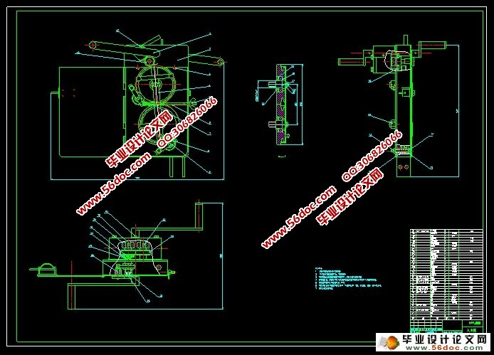
本设计内容包括一级齿轮传动,二级齿轮传动,钢丝绳的绕法,离合器的设计,扇形齿轮传动,蜗杆和蜗杆的自锁。主动轴上的齿轮与传动轴上的齿轮啮合将脚踏上的力和力矩传递到输出轴上。输出轴上的齿轮再将力和力矩通过齿套传递到槽轮的齿轮上,带动槽轮转动,再与下方的齿轮啮合带动下面槽轮的转动,利用钢丝绳与槽轮之间没有相对滑动,从而利用钢丝绳带动整个机器在钢丝绳上下移动。
本设计的特色在于:第一,运用简单的齿轮之间传动比的变化,将人力放大。实现人力能够带动机器升降;第二,扇形齿轮的运用,减小结构,同时起来离合的作用;第三,蜗杆和蜗杆的啮合起到自锁的作用,比起蜗杆蜗轮的自锁功能虽有所欠缺但是相比较而言结构会简化很多,尺寸会精巧甚多。
关键词:升降机;齿轮;传动;蜗杆;自锁;
ABSTRACT
Human elevator has no patent in China, more electricity and power lift hoist have been used. The design of the structure is the traditional combination of innovative ideas and results. Mission is from the practice of social production. Human elevator is used for exterior wall decoration and outdoor power equipment and other special equipment installed. In the case of no power supply can easily manipulate the human upper and lower transport of materials and personnel to fill the lack of product line
This design is mainly taking into account the implementation of function, size limits, structure, simple operation.
First, mechanical principles and mechanical design is based on the theoretical knowledge, Worm gear drive mechanism, Screw Drive as well as several other detailed analysis of common institutions, Choose the appropriate option. The principle according to clutch the clutch mode and select the appropriate bodies Learned to use engineering graphics and three-dimensional mapping of knowledge UG draw assembly drawings, and parts diagram. Finally, we use three-dimensional motion simulation software features for motion simulation, the feasibility of achieving the design. The design includes a gear drive, second gear, Wire rope around the law, the design of the clutch, fan gear, self-locking worm and worm. Take the initiative and drive shaft gear shaft gear mesh on the pedal force and the moment passed on to the output shaft. Output shaft of the gear teeth and then sets of force and torque delivered to the tank through the gear wheel, the drive sheave rotation, then driven gears meshing with the bottom of the tank below the rotating wheel, Re-engagement with the bottom of the drive gear wheel rotation slot below, the use of wire rope and there is no relative slip between the sheaves to drive the entire machine using steel wire rope move up and down.
The design features at: First, the use of a simple gear transmission ratio between the changes in the human enlarge can bring the machine down to achieve human; Second, the use of fan gear, reducing the structure, while the role of up clutch; Third, the meshing worm and worm play a role in self-locking, compared to the self-locking worm gear despite the lack of structure, but the comparison will be simplified a lot, the size will be compact many.
Keywords: hoist;gear;transfer motion; worm; self-locking;
设计方案的制定
由方案想到滑轮组结构,利用钢丝绳绕在滑轮组上由绳带动整个机器实现上下移动。
传动:滑轮组上的齿轮跟输出轴上的齿轮啮合传动,依次一系列的齿轮啮合实现从主动轴(人力脚踏动力)到输出轴再到滑轮组上的齿轮传递动力。
制动:两个蜗杆自锁的原理(螺旋升角小于当量摩擦角)阻止滑轮组的转动
离合控制:由汽车离合原理,将之稍加改动。手柄相当于档位杆,操纵离合器的“开”与“合”离合打开时,滑轮组上的齿轮不能与输出轴上的齿轮啮合,不能传动不能制动,由于机器和人员的自身重力,将加速下降,当离合器合上时,齿轮啮合正常进行,能制动能
传动,机器又回减速下落直到停住。
目录
摘 要 III
ABSTRACT IV
目录 V
1. 绪论 1
1.1 设计背景 1
1.2 设计目的 1
1.3设计内容 2
2.机传动系统的设计提升 3
2.1 工作原理及运动特点 3
2.2 设计方案的制定 5
2.3 人力提升机设计参数的确 5
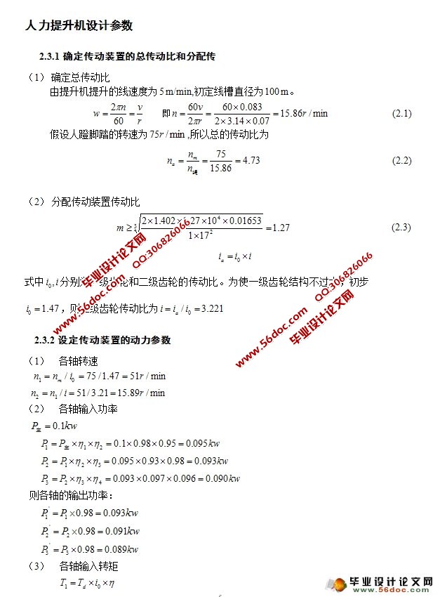
2.3.1确定传动装置的总传动比和分配传 5
2.3.2设定传动装置的动力参数 6
3. 齿轮的设计 8
3.1主动轴上齿轮传动的设计计算 8
3.2 从动轴上齿轮传动的设计和计算 11
3.3 扇形齿轮的设计 15
4. 轴瓦轴承和轴键的设计和校核 20
4.1 主动轴的设计 20
4.1.1 主动轴的设计与校核 20
4.1.2 轴瓦寿命校核: 22
4.2 中间轴的设计 24
4.2.1 中间轴的设计与校核 24
4.2.2 轴瓦寿命校核: 29
4.2.3 键的设计与校核: 31
4.3 从动轴的设计 31
4.3.1 从动轴的设计与校核 31
4.3.2 轴瓦寿命校核 33
4.3.3 键的设计与校核 36
5 传动系统零件的选择和设计 37
5.1选择钢丝绳的型号 37
5.2 箱体结构的设计 37
5.3 润滑密封设计 39
5.4 联轴器设计 40
结论与展望 41
致谢 43
参考文献 44