立式加工中心滑座及X向进给系统结构设计(含CAD图,CAXA图)
无需注册登录,支付后按照提示操作即可获取该资料.
立式加工中心滑座及X向进给系统结构设计(含CAD图,CAXA图)(课题申报表,任务书,开题报告,中期检查表,论文说明书17400字,CAD图纸7张,CAXA图纸7张)
摘 要
数控机床是装备制造业的基础,一个国家数控机床业的水平已经成为衡量该国制造业水平、工业现代化程度的重要标志。立式加工中心是数控机床的集中体现,对它进行研究,可深入了解数控技术及数控机床。但是立式加工中心的工作性能受机床进给系统、滑座等功能部件的直接影响。设计合理的进给系统,滑座结构对提高立式加工中心工作性能有重要的意义。本文主要研究内容如下:
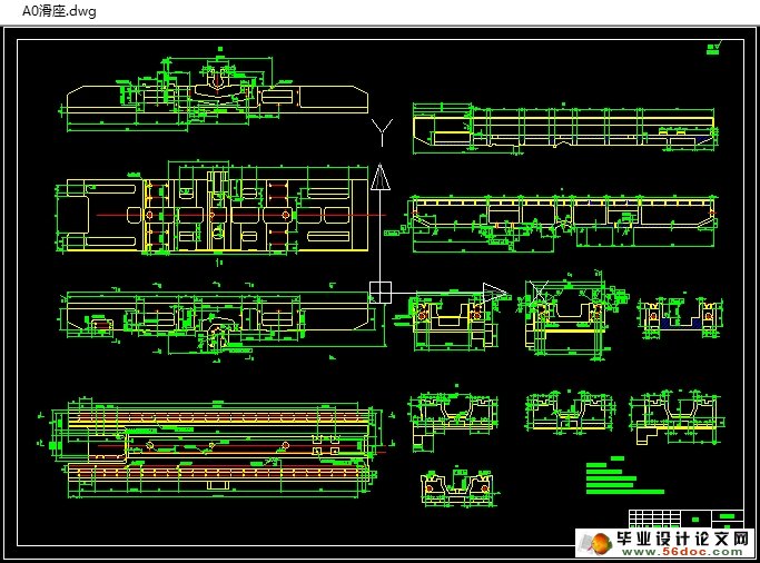
(1)本文对VMC850滑座进行了结构设计及精度设计,并进行了进行了静力计算及有限元分析。
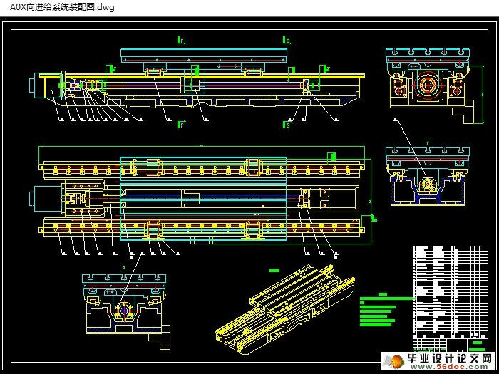
(2)本文对VMC850X向进给系统进行了总体方案设计与零部件设计。
(3)本文对VMC850X向进给系统中伺服电机进行了选择计算与校核。
(4)本文对VMC850X向进给系统中滚珠丝杠副进行了选择计算与校核。
(5)本文对VMC850X向进给系统中滚动轴承进行了选择计算与校核。
(6)本文对VMC850X向进给系统中直线导轨进行了选择计算与校核。
关键词:立式加工中心;滑座;X向进给系统;滚珠丝杠;伺服电机
Abstract
The computer numerical control machine tools is the basis of the equipment manufacturing industry.The level of the CNC machine tools industry has become an important symbol to measure the level of the country's manufacturing industry and the degree of modernization.The vertical machining center is the embodiment of the CNC machine tools. By research it, we can have in-depth understanding of CNC technology and CNC machine tools. But the work performance of the vertical machining center is directly effected by the main function components of vertical machining center, such as the feed system and the slide , etc. The reasonable design of the feed system and the Reasonable structural design of the slide is beneficial to improve the working performance of the Vertical machining center. The main content of this paper as follows:
(1)The structural design and precision design of the slide,the force calculation and analysis of the slide,and finally the finite element analysis of the slide.
(2)The overall program design and the parts design of the X feed system .
(3)The calculate and check of the servo motor of the X feed system.
(4)The calculate and check of the ball screw of the X feed system.
(5)The calculate and check of the rolling bearing of the X feed system.
(6)The calculate and check of the linear guideway of the X feed system.
Key words: The vertical machining center;slide;X feed system;ball screw;servo moto
X向进给系统设计与分析
立式加工中心的性能很大程度上取决于伺服进给系统的性能,因此设计合理的高性能伺服进给系统是加工中心设计成败的关键之一。伺服进给系统是以机床移动部件位置为控制量的自动控制系统,主要有伺服控制电路、伺服驱动装置、机械传动机构及执行部件组成。本章主要对X向进给系统的伺服驱动装置、机械传动机构及执行部件的设计与选用进行详细介绍。
技术参数
X向行程 850mm
X向快速进给速度 32 m/min
工作台长度 1000 mm
工作台宽度 500mm
工作台重量 2290N
工作台最大承重 600 kg
定位精度 0.005/300mm
重复定位精度 0.003mm
最大进给加速时间 0.1s


目录
1 绪论 1
1.1 国产数控机床现状 1
1.2 立式加工中心的特点 2
1.3 研究的意义 3
1.4 本论文的内容 4
2 滑座结构设计 5
2.1 滑座材料选择 6
2.2 滑座结构 6
2.2.1 滑座截面设计 6
2.2.2 滑座肋布置 8
2.2.3 滑座上圆孔和方孔设计 9
2.2.4 滑座壁厚及肋厚度计算 10
2.2.5 滑座最终结构 11
2.3 滑座的静力计算 12
2.4 滑座有限元分析 12
3 X向进给系统设计与分析 17
3.1 X向进给系统总体方案设计 17
3.1.1 技术参数 17
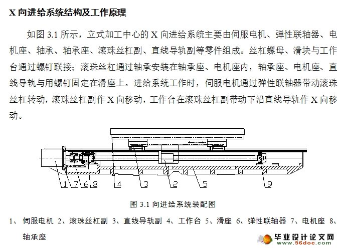
3.1.2 X向进给系统结构及工作原理 17
3.2 滚珠丝杠副的设计计算 18
3.2.1 导程Ph的确定 19
3.2.2 当量载荷及当量转速的计算 20
3.2.3 预期额定动载荷的确定 22
3.2.4 允许最大轴向变形的估算 23
3.2.5 底径d2的估算 23
3.2.6 预紧力Fp的计算 24
3.2.7 其它尺寸的确定 24
3.3 伺服电机的选择计算 24
3.3.1 作用在滚珠丝杠副上转矩的计算 25
3.3.2 负荷转动惯量及传动系统转动惯量的计算 26
3.3.3 加速转矩Ta和最大加速转矩Tam 27
3.3.4 电机的最大启动转矩 27
3.3.5 电机连续工作时的最大转矩 27
3.3.6 电机输出轴直径的计算 28
3.3.7 联轴器的选择 28
3.4 滚动轴承的选择计算 28
3.4.1 初选轴承型号 28
3.4.2 计算轴承的径向载荷Fr和轴向载荷Fa 29
3.4.3 计算当量动载荷Pa和当量静载荷Pao 29
3.4.4 计算寿命L10h 30
3.4.5 校核静载荷 31
3.4.6 校核动载荷 31
3.4.7 校核极限转速 31
3.4.8 游动端轴承的选用 32
3.5 滚珠丝杠的校核 32
3.5.1 传动系统刚度计算 32
3.5.2 传动系统刚度验算 34
3.5.3 滚珠丝杠副压杆稳定性的效验 34
3.5.4 滚珠丝杠副极限转速的校验 35
3.5.5 Dn值校验 35
3.5.6 额定静载荷校验 36
3.6 直线导轨的选用 36
3.6.1 初选导轨型号 37
3.6.2 校核静安全系数fs 37
3.6.3 计算导轨寿命 38
3.6.4 确定导轨型号 39
4 滑座精度要求 40
4.1 滑座加工几何精度要求 40
4.2 滑座装配几何精度要求 41
5 总结 43
致 谢 44
参考文献 45
