油管接头注塑模的设计(CAD,Proe三维)
无需注册登录,支付后按照提示操作即可获取该资料.
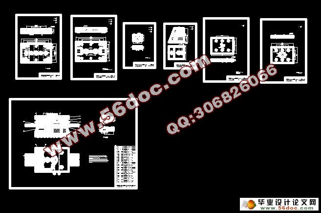
油管接头注塑模的设计(CAD,Proe三维)(任务书,开题报告,中期检查表,设计说明书10000字,工艺卡,cad图纸7张,Proe三维建模)
摘要
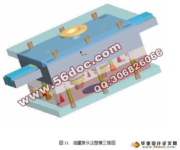
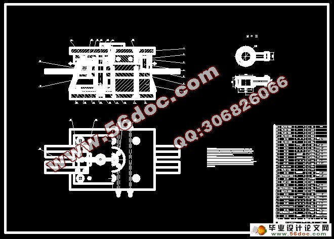
系统介绍了塑件的成形工艺及模具成型结构对塑件质量的影响分析,浇注系统的设计,模具成型部分和总装结构的设计。介绍了油管接头注塑模具设计时要注意的要点,并较多的考虑了模具结构的调整性、易更换性及模具成本。从控制制件尺寸精度出发,对油管接头注塑模的各主要尺寸进行了理论计算,以确定各工作零件的尺寸,从模具设计到零部件的加工工艺以及装配工艺等进行详细的阐述,并应用CAD进行各重要零件的设计。
关键词:工艺分析;塑件成型;浇注系统;模具结构。
Injection Mold for Oil Pipe Junction
Abstract
The molding process of plastic parts, the effect analysis to plastic parts quality caused by molding structure, as well as the casting system design, partial and general design of mold moulding introduced respectively. The critical points of mold for plastic design are introduced, and the adjustable character of molding structure、exchange character as well as the molding costs are all considered farther. Starting from controlling dimensional accuracy, the theoretical calculation to the main dimensions of injection molding are carried out so as to determine the size of different parts, the molding design and the process of parts as well as assembling process and etc of injection molding are stated in details.
Key words: process analysis; plastic parts moulding; casting system; molding structure.
1.1.2 塑件的结构和尺寸精度及表面质量分析
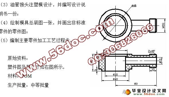
(1) 结构分析。 从零件图上分析,该零件总体形状类示一个三通管道,在下端有一个直径为 35mm,深度为3mm的凹坑。在上端有一个外径为 40mm,内径为 30mm,高度为3mm的凸缘。在三通的一端是一段M12mm的螺纹,其长度为10mm。因此,模具设计时必须设置侧向分型抽芯机构,该零件属于中等复杂程度。
(2) 尺寸精度分析。 从零件图可知,该零件各个尺寸均未注明公差,为提高经济效益,则按未注明公差尺寸来处理。根据表2—15【1】查得POM材料的适用未注公差等级为MT6级(GB/T14486-1993)。从以上分析可见,该零件的尺寸精度等级不高,对应的模具相关零件的尺寸加工容易保证。
从塑件的壁厚上来看,壁厚最大处为9mm,最小处为5mm,壁厚差为4mm,相差较大,成型时可能会在塑件内部产生缩孔和残余应力,应在成型工艺上采取措施,比如延长保压时间和冷却时间,改善浇注系统,开设冷却水道,使模具冷却均匀等,防止缺陷的产生。
(3) 表层质量分析。 该零件的表面要求没有缺陷、毛刺,内部表面应光洁,以利于液体的流动。除此之外没有特别的表面质量要求,故比较容易实现。
综上分析可以看出,注塑时在工艺参数控制的较好的情况下,零件的成型要求可以得到保证。
目录
前 言 1
第1章 模塑工艺规程的编制 4
1.1 塑件的工艺性分析 4
1.2 计算塑件的体积和重量 5
1.3塑件注塑工艺参数的确定 5
第2章 注塑模的结构设计 6
2.1 分型面的选择 6
2.2 确定型腔的排列方式 7
2.3 浇注系统设计 8
2.4 抽芯机构设计 9
2.5 成型零件结构设计 11
第3章 模具设计的有关计算 13
3.1 型腔和型芯工作尺寸计算 13
3.2 螺纹瓣合块的尺寸计算 13
第4章 模具冷却与加热系统的计算 16
第5章 模具闭合高度的确定 17
第6章 注塑机有关参数的校核 18
第7章 绘制模具总装图和非标准零件工作图 19
第8章 注塑模主要零件加工工艺规程的编制 20
第9章 注塑模的装配 21
第10章 试模 22
小 结 23
致 谢 24
参考文献 25
