电炉引线盒冲压模具设计(含CAD零件装配图)
无需注册登录,支付后按照提示操作即可获取该资料.
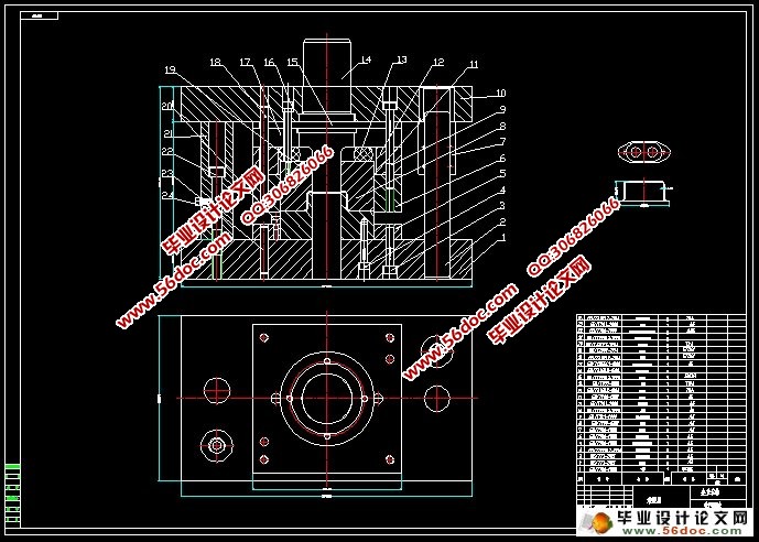
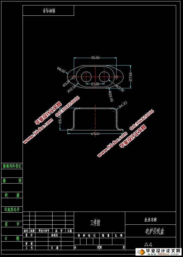
电炉引线盒冲压模具设计(含CAD零件装配图)(论文说明书17000字,CAD图纸9张)
摘 要
首先对冲压件进行分析,分析该零件的尺寸精度得出用一般精度的模具即可满足零件精度的要求,再根据零件的形状、尺寸标注及生产批量等情况,选择落料冲孔的方案。在本次设计冲孔落料复合模中,仅要考虑使做出的零件能满足使用要求,还要保证模具的使用寿命。该冲裁模具还详细地叙述了模具成型零件包括上模架、凹模、凸模、凸模固定板、凸凹模固定板、上模架、下模架、卸料板、模柄等的设计,重要零件的工艺参数的选择与计算,推出机构以及其它结构的设计过程,其中里面也包括了:工艺分析,工艺方案的确定,计算毛坯尺寸,画排样图,计算冲压力,压力机的选择,计算压力中心,凸凹模刃口尺寸的计算,校核冲裁模工作部分,工艺计算冲裁件的毛坯尺寸计算,凸模与凹模的圆角半径,冲裁模中的凸凹模间隙凸、凹模工作尺寸,冲压设备的选择,模具的总体结构,主要零部件的设计及选择,模具制造装配要点等。
关键词:模具设计;冲孔;落料;
Abstract
First of stamping analysis, analysis of the parts size precision are derived using the generalprecision of the mould can meet the requirements of precision parts, according to the shape,dimensions and mass production, selection of blanking punching scheme. In the design ofpunching blanking compound die, only to make the parts can meet the use requirements, but also to ensure that the service life of the die. The blanking die also describes in detail the design of molding parts including the mold, die, punch, punch plate, convex concave die fixing plate, frame, frame of lower, stripper, shank, selection and calculation of technology parameters of the important parts of the design process, introduced the mechanism and itsstructure, which includes: process analysis, to determine the process scheme, calculation of blank dimension, draw the layout, blanking force calculation, press Select, pressure center calculation, calculation of punch and die cutting edge size, check the blanking die workingparts, process calculation of blanking blank size calculation, fillet the radius of the punch and the die, blanking die, die clearance convex concave die size, stamping equipment selection,the overall structure of the mold, design and selection of main parts, mold manufacturingassembly point.
Keywords: punching blanking die design;;


目 录
目 录 4
前言 1
第一章 绪论 2
1.1 概述 2
1.2 冲压技术的进步 2
1.3 模具的发展与现状 3
1.4 模具CAD/CAE/CAM技术 4
1.5 课题的主要特点及意义 5
第二章 冲压工艺分析与计算 6
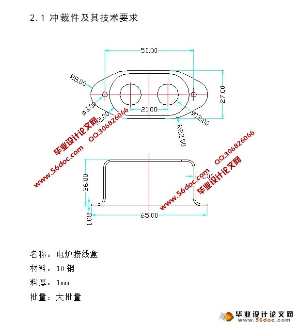
2.1 冲裁件及其技术要求 6
2.2 零件结构工艺分析 7
2.3 冲裁件的排样 9
2.3.1排样方法的确定 9
2.3.2搭边值的确定 9
2.3.3排样方案的选择 10
2.3.4确定条料步距和宽度 11
2.3.5计算条料利用率 12
2.3.6画出排样图 12
2.4 工艺方案的选择 13
2.4.1工艺方案种类 13
2.4.2方案的比较 13
2.4.3方案的确定 13
2.5 填写工艺文件 13
第三章 模具方案设计与计算 14
3.1模具方案设计 14
3.2 模具刃口尺寸计算 14
3.2.1冲孔Φ3mm 14
3.2.2外轮廓的落料 16
3.2.3其它尺寸的计算 17
3.3冲压力计算 19
3.3.1冲孔切口力F1 19
3.3.2落料力F2 19
3.3.3卸料力FX 19
3.3.4推件力FT 20
3.3.5总压力FZ 20
3.4初选冲压设备 22
3.5确定模具的压力中心 22
3.6凸模结构设计 24
3.6.1冲孔凸模设计 24
3.6.2切口刀设计 25
3.9定位零件结构设计 26
3.9.1导料零件设计 26
3.9.2挡料零件设计 26
3.10卸料机构设计 27
3.11推件机构设计 28
3.12模架及组成零件的选用 28
3.12.1模架的选用 28
3.12.2模座的设计选用 29
3.12.3导向零件的设计 30
3.13其它零部件设计 31
3.13.1模柄的选用 31
3.13.2垫板的设计 32
3.13.3固定板的设计 32
3.13.4螺钉、销钉的选用 33
3.13.5弹性元件的选用 33
3.13.6卸料板的设计 35
3.13.7推件块的设计 35
第四章 模具的结构与原理 37
4.1模具各零件名称及材料 37
4.2模具结构介绍 37
4.3模具工作原理 37
第五章 模具的装配 38
5.1冷冲模装配的技术要求 38
5.2 冲模装配的工艺要点 40
5.3 冲模装配顺序的确定 41
5.3.1组件装配 41
5.3.2下模装配 41
5.3.3上模装配 41
5.3.4其他零部件组装 42
5.4 冲模的调试 43
第六章 模具零件加工工艺 44
6.1工作零件的制造工艺 45
第七章 结论 46
参考文献 47
致谢 48
