
��ѹ������˸Ǹ���ģ���(��cad���ͼ��װ��ͼ)
����ע���¼,֧��������ʾ�������ɻ�ȡ������.
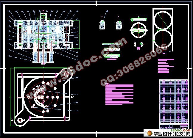
��ѹ������˸Ǹ���ģ���(��cad���ͼ��װ��ͼ)(ѡ��������,������,���ⱨ��,���ڼ���,˵����13900��,CADͼֽ12��)
ժ Ҫ�����ڴ˴���Ƶı�ѹ������˸��м�����ṹ��������������У��������ƴʽģ��ʹ�����������Ρ�ģ�߲���˳װ�ṹ�����ö���װ�ô�������ʹ����������ͨ��������ѹ������˸ǵĽṹ�ͳ��ι��գ�����ë���ߴ硢��ѹ�����пڳߴ磬��Ƴ���һ�����ϡ�������������Ϊһ��ĸ���ģ��ģ�߽ṹ����������ƹ����У��ص�����乤�սṹ��������ṹ���������ģ����ǿ�Ƚ��м�������֤������ԣ��Ӷ���֤����Ʒ����������߶˸ǵ�����Ч�ʡ�
�ؼ��ʣ��˸Ǹ���ģ�����ϣ�������
Design of Composite Mould For Transformer Oil Storage Cabinets Cover
Abstract: In this design,there is a raised structure in the middle of the transformer oil storage cabinets cover. So it is needed a mosaic-style punch to make the workpiece possible to rip plastic and reshaped in the drawing process. The mould is in a smooth structure.In other words,taking the pin-lift arrangement to push out the workpiece from the bottom up to the top.Through the analysis of the structure of the transformer oil storage cabinets and the craftwork of figuration,and through the calculation the rough size,pressure and the cutting edge size A compound die structure combined with blanking,drawing,punching the three processes as an arganic whole was carried out..In this whole design process, the mould’s structural components and supporting structure is the roughcast priority excogitation.At last,by checking the strength of the mould in order to prove its possibility to contribute the products high quality and develop the cover productivity.
Key words: the composite mould for the cover;blanking; deep drawing; punching
����ͼֽ����
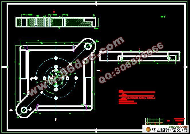
��ѹ������˸ǵIJ���Ϊδ���˻��Q235�ӽ�����������Ϻ��Ϊt=2mm��
���������ϴ������ͼ����ҳͼ����ʾ��
��ͼ1֪��������ṹ��Ϊ���ӣ�����Բ����ֱ����ɣ��Գƣ�ͼ�ϳߴ���1~180�L���ݽ̲ġ����ѹģ����������죨��2�棩����7ҳ����2.3����֪�ó�ü����������ܴﵽ�ľ��þ���ΪIT11—IT14���������ͼ�Ͽױ߾���ľ�Ϊ120±0.5����120mm�Ĺ���Ϊ±0.5����IT12�����ȣ����ͼ������δ��ע����ijߴ磬�������ɳߴ�


Ŀ ¼
ժ Ҫ 1
�ؼ��� 1
1 ǰ�� 2
2 ���������Է��� 2
2.1 ����ͼֽ���� 2
2.2 ����˳���ȷ�� 3
3 �ƶ����շ��� 4
3.1 ���շ����ķ��� 4
3.1.1�ޱ������ļ��� 4
3.1.2ë���ߴ�ļ��� 4
3.1.3ȷ������ϵ�� 8
3.1.4ȷ���Ƿ�ʹ��ѹ��Ȧ 9
3.2 ���շ�����ȷ�� 9
4���ռ��� 9
4.1 �������������������ʵļ��� 9
4.2 ȷ�����Ϲ��Ͳ��Ϸ�ʽ 10
4.3 ѹ�����ĵļ��� 10
4.4 �пڳߴ��빫��ļ��� 11
4.4.1���� 11
4.4.2���� 12
4.4.3��� 12
4.5 ��ѹ���ļ��㼰��ѹ�豸�ij�ѡ 13
4.5.1���� 13
4.5.2���� 14
4.5.3��� 15
5 ģ��������� 16
5.1 ģ���������̵ķ��� 16
6 ģ����Ҫ�㲿���Ľṹ��� 16
6.1 ģ������������� 16
6.1.1����ģ 16
6.1.2���ϰ�ģ 17
6.1.3����ģ 17
6.1.4���ģ 17
6.1.5���ģ 18
6.1.6��װ�ģ 18
6.2 ��װ������������ 18
6.2.1ģ������� 18
6.2.2ģ�ܵ���� 18
6.2.3�ϡ���ģ������� 18
6.2.4�̶������� 19
6.2.5������� 19
6.2.6�ݶ������ 19
6.2.7��������� 20
6.3 ������������ 20
6.3.1���� 20
6.3.2���� 20
6.4 ж�ϺͶ���װ�õ���� 21
6.4.1ж��װ�õ���� 21
6.4.2����װ�õ���� 22
7 ģ��ǿ��У�� 23
7.1 ���ģ��ǿ��У�� 23
7.2 �ݶ���ǿ��У�� 23
8 ��ѹ�豸��ѡ�� 24
8.1 ѹ�������͵�ѡ�� 24
8.2 ѹ��������ȷ�� 24
9 ���� 25
����� 25
�� л 26
�� ¼ 26