立式精锻机自动上料机械手设计(三维Proe)☆
无需注册登录,支付后按照提示操作即可获取该资料.
摘 要
本文介绍了立式精锻机自动上料机械手与其它设备的配置关系及工作过程,并对机械手的动作进行了分析,详细论述了机械手总体方案的设计,特别是对实现预期要求动作的各种方案进行了比较分析,进而得出最终方案。根据手臂的动作要求,采用圆柱坐标型机械手;机械手的自由度数为四个,它们是大臂的升降和回转运动,小臂的伸缩运动,手腕的回转运动;机械手手部结构采用两支点回转型;机械手驱动方式采用液压驱动。控制方式为点位程序控制。本次设计主要进行大臂升降及回转机构设计、手臂及伸缩结构设计、手部结构设计,并且对液压系统进行理论分析和比较。
关键词:双作用式油缸;点位控制;液压系统;结构设计
Abstract
Industrial manipulator is a kind of automatic devices, which substitutes people to carry out dangerous or duplicate work. It complies crawler tracks、handling work or manage or operate a tool according to set procedures and requirements. It is constituted with executive body、drive system and control system. In this paper, it has shortly introduced the position connection and work process between manipulator and other equipments. It has also given a relatively minute discussion of the manipulator overall plan, especially have compared the different projects to realize the require action and then given out the final scheme. According to the motion requirements of the manipulator’s arm, it has adopted cylindrical coordinate manipulator. The number of the manipulator’s freedom is four: up-down and rotating of the big arm, the straight reciprocating motion of the small arm, revolving movement of the wrist. The fingers of the manipulator have adopted the two-points sustain round structure. The power drive of manipulator is to be used is hydraulic system and control program for points for control type. This design is mainly consist of the design of large arm take-off and landing and rotating, the structural design of arm and telescopic arm, structural design of hand. What I mainly design is the structural design of large arm take-off and landing and rotation, and I carry out the theoretical analysis and comparison of hydraulic system.
Key words:Double-acting oil cylinder; Point-to-point control; Hydraulic system ; Structural design
2 系统设计方案
2.1 机械手的设计参数
抓重:60kg;
自由度数:4个;
坐标形式:圆柱坐标;
最大工作半径:1700毫米;
手臂最大中心高:2300毫米;
手臂运动参数;
手臂伸缩范围:0~500毫米
手臂伸缩速度:伸出176毫米每秒;
手臂升降范围:0~600毫米;
手臂升降速度:上升102毫米每秒;
下降152毫米每秒;
手臂回转范围:00 ~2000 (实际使用为950);
手臂回转速度:630每秒;
手腕运动参数:
手腕回转范围: 0~180
手腕回转速度: 200/s
手指夹持范围 30~120mm
缓冲方式及定位方式:
手臂伸缩:伸出时由行程开关适时切断油路,手臂缓冲,缩回时由行程开关控制返回终了位置。
手臂升降:上升时是靠可调碰铁触动行程开关而发信,使电液换向阀变为“o”型滑阀机能,切断油路而实现缓冲定位,下降时靠油缸端部节流缓冲,由行程开关控制终了位置。
手臂回转:采用行程节流阀(双向使用)减速缓冲,用定位油缸驱动定位销而定位。
手腕回转:采用行程开关发信,切断油路滑行缓冲,死挡块定位。
驱动方式:液压
控制方式:点位程序控制
2.2机械手的工艺流程
机械手原位→机械手前伸→机械手上升→机械手抓取并夹紧→机械手后退
机械手左转→机械手前伸→机械手松开→机械手下降→机械手右转→退至原位
2.3机械手的总体结构
本机械手系统由执行系统、驱动系统和控制系统组成。执行系统包括手部、手臂、手腕。驱动系统包括动力源、控制调节装置和辅助装置组成。控制系统由程序控制系统和电气系统组成。
1)自动上料机械手的组成
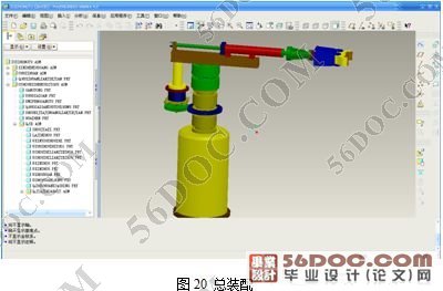
它是由手臂升降机构 1,中间座部件 2,手臂回转机构(由回转油缸 3 和行星轮系及回转定位油缸 4 等组成),手臂伸缩机构 5,手腕 6 和夹持式手部 7 等部分组成。
2)自动上料机械手手臂升降机构
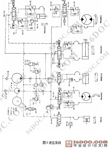
该机构采用双作用式油缸实现垂直升降运动,其行程最大为600mm。升降机构的结构如图所示,升降缸体与缸体支撑座用螺钉联接;活塞杆的上端通过球形铰链,上球形铰座,连接盘和导向套等组成升降机构的运动部分。当压力油分别进入升降缸上下两腔后,推动活塞杆并带动导向套一起做升降运动。在导向套上安装有导向键,它能在缸体支撑座上的键槽内滑动,用此键防止导向套升降时可能出现的转动。用导向套作导向装置,其导向性能好,刚度大工作平稳。活塞杆与连接盘间用球型铰链联接,可自动弥补导向套倾斜所引起的偏差,使活塞杆升降时滑块。手臂下降运动的缓冲由油缸底部的缓冲调节阀来实现。手臂升降行程是通过安装在侧板上的可调撞块和行程开关来控制。
目 录 22000字
摘 要 I
Abstract II
1 绪 论 1
1.1 机械手的基本概念 1
1.2机械手的分类及简史 2
1.2.1 机械手的分类 2
1.2.2 机械手的简史 4
1.3 机械手的应用简况 5
1.4 机械手的发展趋势 5
1.5机械手的组成 7
1.5.1执行机构 7
1.5.2驱动机构 8
1.5.3控制系统 9
1.6应用机械手的意义 9
2 系统设计方案 11
2.1 机械手的设计参数 11
2.2机械手的工艺流程 12
2.3机械手的总体结构 12
2.4机械手的工作过程 15
2.5机械手的座标型式与自由度选择 17
2.6机械手的手部结构方案设计 17
2.7机械手的手腕结构方案设计 17
2.8机械手的手臂结构方案设计 17
2.9机械手的驱动方案设计 17
2.10机械手的控制方案设计 18
3 机械手结构设计 19
3.1 机械手材料 19
3.1.1 机械材料选用原则 19
3.1.2零件材料 21
3.2传动方式 22
3.2.1带传动 22
3.2.2链传动 23
3.2.3 齿轮传动 23
3.2.4 杆传动 24
3.3机械手手部设计 25
3.3.1手部结构 25
3.3.2夹紧力计算 25
3.3.3夹持误差 26
3.3.4机械手腕部设计 26
3.3.5手臂的设计计算 27
3.4液压缸系统设计 28
3.4.1液压系统的工作原理 28
3.4.2液压传动的工作特性 28
3.4.3液压系统的组成 29
3.4.4液压系统的优、缺点 29
3.4.5液压传动的主要缺点 30
3.4.6自动上料机械手液压系统 30
3.4.7液压缸计算 32
3.4.8液压缸壁厚计算 33
3.5机械手转轴强度校核 35
3.6机械手联结键校核 38
3.7传动轴校核 38
3.8轴承校核 41
4 主要零部件三维制作过程 43
4.1 回转缸绘制过程 43
4.2手部结构及加紧缸的绘制过程 46
4.3简单连接件的绘制过程 49
4.4总装图的绘制 50
5 机械手控制策略 51
5.1 末端执行器控制策略 51
5.1.1 传感器 51
5.1.2 末端执行器控制策略 52
5. 2 机械手控制策略 53
6 结论和展望 54
6.1 结论 54
6.2 展望 54
参考文献 55
致 谢 56
