低压长袋脉冲除尘器的电控系统设计(含CAD控制图梯形图)
无需注册登录,支付后按照提示操作即可获取该资料.
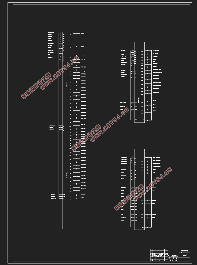
低压长袋脉冲除尘器的电控系统设计(含CAD梯形图IO分配图)(论文说明书27000字,外文翻译,CAD图4张)
摘 要
我省实施的《燃煤电厂大气污染物排放标准》中,对污染物排放浓度制订了各种指标,其中燃煤发电锅炉烟尘为5mg/m³、二氧化硫为35 mg/m³、氮氧化物的排放限量为50mg/m³,并要求在烟囱和烟道处安装污染物排放监控。很多小型电厂因排放达不到环保要求,被迫停产。
随着国民经济的发展以及越来越严格的环境保护要求,由于袋式除尘器除尘效果非常好,所以在很多工业部门广泛应用。
文章介绍了低压长袋脉冲除尘器的研究动态,概述了不同的除尘方式所具有的特点。概述了低压长袋脉冲除尘器的工作原理,同时完成了系统的硬软件设计、调试仿真等。
关键词:袋式除尘器;PLC控制;仿真
Design of electric control system of low pressure long bag pulse dust collector
ABSTRACT
In the emission standards of air pollutants from coal-fired power plants implemented in our province.A variety of indicators have been developed for pollutant emission concentration, among which soot from coal-fired power generation boiler is 5 mg/m³、Sulfur dioxide is 35 and The nox emission limit is 50. Requires installation of pollutant discharge monitoring at chimneys and flues. Many small power plants have been shut down because their emissions have failed to meet environmental requirements.
With the development of national economy and more and more strict requirements of environmental protection, bag filter is widely used in many industrial sectors because of its good effect。
This paper introduces the research trends of the low pressure long bag pulse precipitator and summarizes the characteristics of different dedusting methods.The working priniple of the low pressure long bag pulse precipitator is summarized,and the hardware sofware design,debugging and simulation and of the system are completed.
The keyword:Bag filter;PLC control;The simulatio


目 录
摘要 i
ABSTRACT ii
1 概述 1
1.1 安装除尘设备的目的与背景 1
1.2 袋式除尘器在电厂中的应用 1
1.3 国内外研究动态 2
2 除尘器 5
2.1 除尘器的分类 5
2.1.1 各类除尘器的结构和工作原理 5
2.2 采用低压长袋脉冲除尘器的原因 19
2.3 袋式除尘器的定义与分类 20
2.3.1 袋式除尘器的定义 20
2.3.2 袋式除尘器的分类 20
2.4 低压长袋脉冲除尘器的结构与工作原理 24
2.4.1 低压长袋脉冲除尘器的结构与特点 24
2.4.2 低压长袋脉冲除尘器的工作原理 24
3 所用控制硬件介绍 27
3.1 差压传感器 27
3.2 可编程脉冲控制仪 27
3.3 脉冲电磁阀 28
3.4 压力传感器 29
3.5 温度传感器 30
3.6 提升阀 31
4 电控系统的硬件设计 33
4.1 PLC的发展与特点 33
4.2 PLC的分类 35
4.3 硬件的选择与系统组成 37
4.4 I/O分配图 40
4.5 除尘系统的控制流程图 45
4.6 I/O分配表 46
5 电控系统的软件设计 50
5.1 GX WORKS2编程软件介绍 50
5.2 软件系统的组成及程序设计 50
5.2.1 提升阀控制系统 50
5.2.2 除尘喷吹控制系统 51
5.2.3 压缩空气系统设计 53
5.2.4 氧量仪监测系统 55
5.2.5 压力监测报警系统 55
5.2.6 温度监测系统 56
5.2.7 旁路系统 58
5.2.7 灰位监测系统 59
5.2.9 引风系统 60
5.3 组态王6.55(Kingview)介绍 61
5.4 组态仿真画面 62
5.5 程序仿真与结果反馈 65
参考文献 69
附录 71
外文文献 88
中文翻译 95
致谢 101
