基于FPGA的实时电话计费器的设计
无需注册登录,支付后按照提示操作即可获取该资料.
基于FPGA的实时电话计费器的设计(任务书,开题报告,论文说明书11500字)
摘 要
实时电话计费系统是现代通信管理的一个重要组成部分,一个实时电话计费系统的主要组成部分有控制系统、显示系统和报警系统。不断发展的FPGA具有成本低、设计周期短、可靠性高和集成度高的优点。本文采用FPGA技术完成一个实时电话计费器的设计,使其能够对卡内余额进行快速充值,并根据用户当前的通话种类和通话时间进行扣费,再将通话时间、实时余额和通话方式通过LCD显示。
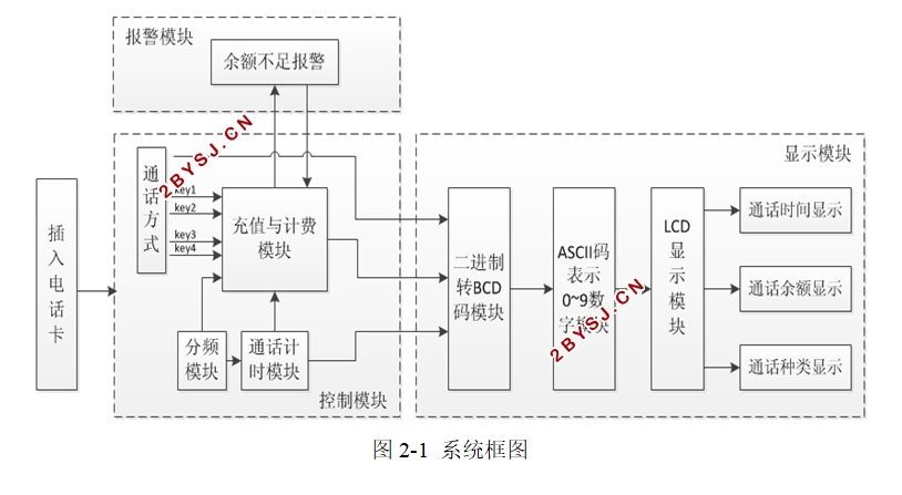
本次设计在Xillinx ISE开发环境下,采用自顶向下,分层次化、分模块的设计方法,将整个系统分为控制模块、显示模块和报警模块这三大模块,采用Verilog HDL语言编写程序,在Modelsim平台上进行仿真,最后在Spartan-3E Starter Kit Board上进行硬件调试。
关键词:电话计费器 现场可编程门阵列 Verilog HDL
The Design of Real-time Phone Call Meter Based on FPGA
ABSTRACT
System of real-time phone call meter is an important component of modern communication management, while control system, display system, and alarm system are main components of system of real-time phone call meter. The continuous development of the FPGA has the advantages of low cost, short design cycle, high reliability, and high integration level; In the paper a method is proposed to use FPGA technology to complete the design of real-time phone call meter, which can quickly be recharged, deduct expense according to current call type and call time, then display call time ,real-time balance and call method through LCD.
The whole design is developed on Xillinx ISE,and the design method is up-to-down, different-level, and different-module. The whole system is divided into control module, display module, and alarm module.VerilogHDL is used in this design to programming. It is simulated with the Modelsim software, and debuggde on Spartan-3E Starter Kit Board finally.
Key words:phone call meter; FPGA; Verilog HDL


目录
摘 要 I
ABSTRACT II
第一章 绪 论 1
1.1课题背景 1
1.2课题研究意义 1
1.3课题研究内容 2
1.4课题研究工具 2
第二章 系统分析 3
2.1电话计费器系统设计要求 3
2.2电话计费器系统设计过程和方法 3
2.3电话计费器系统框图 4
第三章 模块设计 5
3.1控制模块的设计 5
3.1.1充值与计费模块 5
3.1.2分频模块 7
3.1.3计时模块 9
3.2显示模块的设计 10
3.2.1二进制转BCD码模块 10
3.2.2 ASCII码表示0~9数字模块 12
3.2.3 LCD显示模块 13
3. 3报警模块的设计 16
3.4系统总模块图和原理图 16
第四章 仿真与调试 18
4.1控制与报警模块的仿真 18
4.1.1充值仿真 18
4.1.2市话正常通话与报警仿真 18
4.1.3国内长话正常通话与报警仿真 19
4.1.4国际长话正常通话与报警仿真 20
4.1.5特殊种类正常通话与报警仿真 21
4. 2显示模块的仿真 22
4.2.1 二进制转BCD码仿真 22
4.2.2 ASCII码表示0~9数字仿真 23
4.2.3 LCD显示仿真 23
4. 3调试 24
4.3.1硬件框图与实物图 24
4.3.2调试过程中问题与解决 26
结束语 28
参考文献 29
致谢 30
附录 31
