
程控增益宽带放大器的设计
无需注册登录,支付后按照提示操作即可获取该资料.
程控增益宽带放大器的设计(论文10000字)
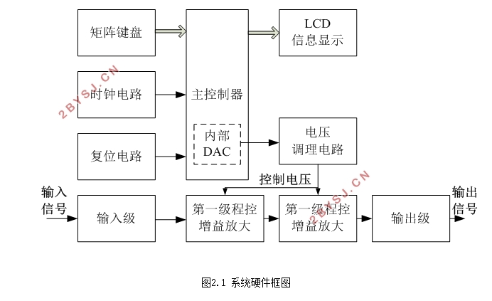
摘要: 宽带放大器在仪器仪表电路中应用广泛,常用来作为信号的调理电路。为适应不同幅度范围的输入信号,需要设计增益可程控的放大器。本系统以可编程增益的运放AD603为核心,选用MSP430F169低功耗单片机作为主控,利用内部DAC模块产生增益控制电压,通过运放调理后控制两级程控运放的增益,且系统的输入和输出电阻均为50Ω,实现了阻抗匹配。论文提出了系统电路原理图,并对增益和控制电压的关系进行了分析和计算。实验测试表明,系统的增益控制范围为-20dB~60dB,以10dB步进,带宽达到40MHz。所设计的电路可用于频率计、示波器等仪器的前端处理电路。
关键词: AD603,程控增益,宽带放大,单片机
Design of Programmable Gain Broadband Amplifier
Abstract Broadband amplifier in the instrumentation circuit is widely used,commoniy used as a singnal conditioning circuit.In order to adapt to different amplitude range of the input signal,we need to design the gain programmble amplifier.The system uses the programmble gain opamp AD603 as the core,choose MSP430169 low-power Single Chip Microcomputer as the master,the use of internal DAC module to generate the gain control voltage,through the opamp after control of two-stage programmable op amp gain, and the system input And the output resistance is 50Ω, to achieve the impedance matching. In this paper, the circuit diagram of the system is put forward, and the relationship between the gain and the control voltage is analyzed and calculated. Experimental tests show that the system gain control range of -20dB ~ 60dB, 10dB step, bandwidth up to 40MHz. The design of the circuit can be used for frequency meter, oscilloscope and other equipment front-end processing circuit.
Keywords:AD603,Programmble gain,Broadband zoom,Single Chip Microcomputer

目 录
第一章 引言 4
1.1 研究背景与研究意义 4
1.2 研究现状 4
第二章 设计方案论述 5
2.1 系统设计的任务与要求 5
2.2 设计方案 5
2.2.1 可控宽带增益方案选择 5
2.2.2 设计系统框图 5
第三章 系统硬件电路设计 6
3.1主控制器模块电路 6
3.1.1 复位电路 8
3.1.2 时钟电路 8
3.2 程控放大电路模块设计 9
3.2.1 设计方案 9
3.2.2 三级放大电路 10
3.2.3 50Ω阻抗匹配 11
3.3 增益控制电压产生及调理电路 12
3.3.1 增益控制电压产生电路 12
3.3.2 调理电路 13
3.4 电源模块设计 13
3.3.1 +5V 电源电路 14
3.3.2 +3.3V电源电路 14
3.3.3 -5V电源电路 15
3.4显示模块 15
3.5 按键电路模块 17
第四章 系统软件设计 18
4.1 主函数软件流程图 18
4.2中断模块程序流程 19
第五章 系统调试 20
5.1 硬件电路的制作 20
5.1.1 制作PCB 20
5.2.2 系统焊接 21
5.2.3 硬件电路粗检测 21
5.2.4电源检测 21
5.2.5硬件部分的连接 21
5.2 调试 21
5.2.1 放大特性检测 21
5.2.2 测试所得增益与控制电压关系式 23
第六章 总结 24
参考文献 25
致谢 26