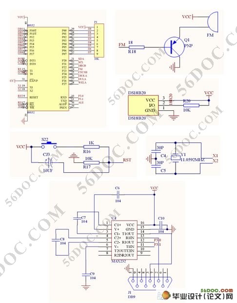
基于GSM网络的远程温度监测系统设计(电路图,程序)
无需注册登录,支付后按照提示操作即可获取该资料.
基于GSM网络的远程温度监测系统设计(电路图,程序)(任务书,开题报告,中期报告,毕业论文,21000字,程序)
摘 要
高性能温度监测的基础在于对现场参量准确的测量及报警。本文设计了一种基于单片机和GSM网络的智能温度监测系统,包括硬件设计和软件设计。系统采用 STC89C51单片机作为主芯片,TC35i模块作为GSM网络远程报警器,DS18B20数字温度传感器作为温度采集器件,运用蜂鸣器作为声音报警器,共阳型四位数码管作为显示屏。可实现温度监测、故障分析以及超限报警并通过GSM网络进行远程报警;设有键盘和显示电路,用来实现温度值的设定、调节和显示当前温度值的功能。实验表明该系统具有结构简单、性能稳定可靠、使用方便等特点。
关键词:单片机,温度传感器,GSM,远程报警
ABSTRACT
High-performance temperature monitoring is based on accurate measurement on-site parameters and alarm. This paper presents a based on microcontroller and GSM networks intelligent temperature monitoring system, including hardware design and software design. The system uses a STC89C51 as the main chip, a TC35i module as a remote annunciator for GSM network, a DS18B20 digital temperature sensor as the temperature acquisition device, the use of the buzzer as the Annunciator sounds,a LED digital as a screen. Temperature monitoring and failure analysis as soon as limit alarm can be achieved.The sisyem has a keyboard and display circuit, used to achieve the set temperature and displays the current temperature. Experiments show that this system is simple for easy to use and the performance is stable and reliable.
Keywords: microcomputer,temperature sensor, GSM, remote alarm
该系统的软件设计采用C语言实现。分主程序与子程序,子程序中又主要包括DS18B20温度采集程序、数码管显示程序、蜂鸣器报警程序、GSM短消息程序等几个子程序模块。
根据系统设计功能的要求,系统由5大模块组成:
1)核心控制单元STC89C51RC模块;
2) GSM无线通信模块;
3)传感器数据信息采集模块;
4)报警模块;
5)数码管显示模块。
GSM模块中电源电路分为充电电池和稳压电源模块两部分:充电电池主要为整个系统提供3.6V工作电压,同时产生MAX3238所需要的高电平;三端电源模块LM7806将外部+12V直流电源转换为+6V,连到ZIF连接器的11、12引脚,在充电模式下,为TC35i提供+6V、500mA的充电电源。
启动电路由开漏极三极管和上电复位电路组成。模块上电10ms后(电池电压须大于3V),为使之正常工作,必须在15脚()加时长至少为100ms的低电平信号,且该信号下降沿时间小于1ms。启动后,15脚的信号应保持高电平。


#p#副标题#e#
目 录
摘 要 I
ABSTRACT II
第1章 引言 1
第2章 相关技术介绍 2
2.1 系统原理 2
2.2 核心控制单元89C51单片机 2
2.2.1 89C51单片机概述 3
2.2.2 89C51单片机特性 3
2.2.3 89C51单片机引脚功能与封装 4
2.3 GSM无线通信模块——TC35i 6
2.3.1 AT指令说明 7
2.3.2 PDU编码规则 8
2.3.3 单片机与TC35i的软件接口及控制原理 9
2.3.4 RS-232串行接口 9
2.4 温度传感器DS18B20 12
2.4.1 DS18B20特点 12
2.4.2 DS18B20引脚及管脚功能介绍 13
2.4.3 DS18B20内部结构简要介绍 13
2.4.4 DS18B20的测温原理 14
2.4.5 DS18B20的读写操作介绍 14
2.5 报警模块——蜂鸣器 16
2.5.1 蜂鸣器的介绍 16
2.5.2 蜂鸣器选择 16
2.6 显示模块——四位共阳极数码管 17
第3章 硬件电路设计 20
3.1 温度检测电路 20
3.2 键盘、显示电路 20
3.2 GSM网络远程报警电路 21
第4章 系统程序设计 22
4.1主程序流程图 22
4.2 中断子程序流程图 23
4.2.1 DS18B20温度采集子程序 23
4.2.2 数码管显示子程序 23
第5章 系统调试 25
5.1 硬件测试 25
5.2 软件测试 26
5.3 系统调试 26
第6章 测试结果 27
结 论 28
参考文献 29
附录1:各部分电路图 30
附录2:源程序 32
致 谢 44
