
基于单片机的交通灯控制器的研究与设计
无需注册登录,支付后按照提示操作即可获取该资料.
摘要: 近年来随着科技的飞速发展,单片机的应用正在不断地走向深入,同时带动传统控制检测日新月异更新。在实时检测和自动控制的单片机应用系统中,单片机往往是作为一个核心部件来使用,仅单片机方面知识是不够的,还应根据具体硬件结构,以及针对具体应用对象特点的软件结合,加以完善。
十字路口车辆穿梭,行人熙攘,车行车道,人行人道,有条不紊。那么靠什么来实现这井然秩序呢?靠的是交通信号灯的自动指挥系统。交通信号灯控制方式很多。本系统采用MSC-51系列单片机Intel8031和可编程并行I/O接口芯片8255A为中心器件来设计交通灯控制器,实现了能根据实际车流量通过8031芯片的P1口设置红、绿灯燃亮时间的功能;为了系统稳定可靠采用了MAX629“看门狗”芯片,避免了系统因为死机而停止工作的情况发生;显示时间直接通过8255的PA、PB口输出;交通灯信号通过PC口输出;交通灯的点亮采用VT双向晶闸管来控制,直接采用220V交流电源驱动,系统实用性强、操作简单、扩展性强。
关键词:单片机 交通灯 控制器 设计 实现
Based on the design of the controler of traffic lights of single flat machine
with realization
TANG Bo
(Grade 2001 ,Computer Science and Technology[Educational direction], College of Mathematics and Computer Science,Chongqing Three Gorges University ,Wanzhou, Chongqing 404000)
Abstract: In recent years along with science and technology develop fast, the application of single flat machine is moving towards thorough continuously, at the same time drive traditional control detection day the benefit of new moon update. In the only flat machine application system of the automatic control and detection of real time, only flat machine is often to use as a key parts, only single flat machine aspect knowledge is insufficient , return should basis specificly hardware structure, as well as aim at the software that applies object characteristic specificly combination, perfect.
Crossroads vehicle wear comb, pedestrian Xi Rang, turn to be all right lane, person pedestrian says , methodically. Do you lean what to realize this orderly order? What lean is that the automatic command system of traffic signal lamp. Traffic signal lamp control way is many . This system adopts MSC-51 series only flat machine Intel8031 with but programming parallel interface chip 8255 A of I/O is central device the design controler of traffic lights, haverealized can measure according to actual wagon flow the P1 installation bonus and green light that passes through 8031 chips burn to light the function of time; For system stabilize reliable have adopted MAX629 the chip " dog looks after the house ", have avoided that system stops working condition because of halting to occur; Show that time is directly exported through PB and PA of 8255; The signal of traffic lights is exported through usually PC mouth; The point of traffic lights light to adopt VT two-way Jing floodgate pipe come to control, directly drive with the alternating current source of 220 V, practicality is strong, operating is simple.
Keywords: Only flat machine Traffic lights Controler Design Realize
系统工作原理
(1)开关键盘输入交通灯初始时间,通过8031单片机P1输入到系统
(2) 由8031单片机的定时器每秒钟通过P0口向8255的数据口送信息,由8255的PC 口显示红、绿、黄灯的燃亮情况;由8255的PA、PB口显示每个灯的燃亮时间。
(3)8031通过 设置 各个信号等的燃亮时间、通过8031设置,黄、绿、红时间依次为3秒、60秒、3秒、80秒、3秒循环由8031的 P0口向8255的数据口输出。
(4) 通过8031单片机的P3.0位来控制系统是工作或设置初值,当.牌位0就对系统进行初始化,为1系统就开始工作。
(5)8255PA口用于输出时间的个位,PB口用于输出时间的十位,由747S07驱动芯片驱动;.而PC口用于输出各个灯的情况,它的末段连接双向晶闸管采用220V交流电压驱动。
(6)在交通控制程序中加入看门狗指令,当系统出现异常看门狗将发出溢出中断。通过专用端口输入到MAX692看门狗芯片的WDI 引角引起RESET复位信号复位系统
本系统就是充分利用了8031和8255芯片的I/O引角。系统统采用MSC-51系列单片机Intel8031和可编程并行I/O接口芯片8255A为中心器件来设计交通灯控制器,实现了能根据实际车流量通过8031芯片的P1口设置红、绿灯燃亮时间的功能;为了系统稳定可靠采用了MAX629“看门狗”芯片,避免了系统因为死机而停止工作的情况发生;显示时间直接通过8255的PA、PB输出;交通灯信号通过平常PC口输出;交通灯的点亮采用VT双向晶闸管来控制,直接采用220V交流电源驱动,系统设计简便、实用性强、操作简单、程序设计简便。系统不足之处不能控制车的左、右转、以及自动根据车流改变红绿灯时间等。这是由于本身地理位子以及车流量情况所定,如果有需要可以设计扩充原系统来实现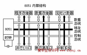


目 录
摘要 ................................................................... I
Abstract.................................................................II
1 引言 .................................................................1
2 单片机概述 ........................................................... 1
3 芯片的选者与简介......................................................1
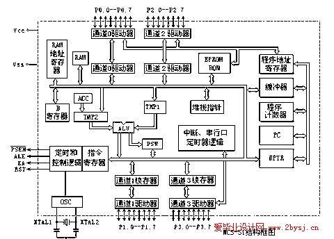
3.1 MSC-51芯片简介.....................................................1
3.2 8255芯片简介.......................................................4
3.3 其他器件...........................................................5
4 控制器硬件的设计.......................................................5
4.1交通管理方案论证....................................................5
4.2系统硬件设计........................................................6
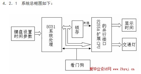
4.2.1交通灯系统框图..................................................6
4.2.2交通灯控制线路图................................................7
4.2.3系统工作原理....................................................8
5控制器的软件设计........................................................8
5.1每秒钟的设定.........................................................8
5.2计数器的硬件延时.....................................................8
5.2.1计数器初值计算...................................................8
5.2.2计算公式.........................................................8
5.2.3设置1秒的方法...................................................8
5.2.4相应代码程序.....................................................9
5.3软件延时............................................................9
5.4时间及信号灯的显示..................................................10
5.4.1 8031并行口扩展.................................................10
5.4.2显示原理........................................................10
5.4.3 8255输出信号的放大.............................................10
5.4.4 8255输出信号与信号灯的连接.....................................11
5.4.5 8255与8031的连接...............................................11
5.5程序设计............................................................11
5.5.1流程图如图所示..................................................11
5.5.2 程序源代码..................................................... 12
6看门狗硬件电路设计.....................................................16
6.1软件看门狗....................................................... 17
6.2硬件看门狗....................................................... 17
7单片机开发系统.........................................................19
8实验平台...............................................................20
8.1实验平台...........................................................20
8.2实验步骤 ..........................................................20
8.3 系统编程信息...................................................... 20
8.3.1 系统内存分配和I/0接口使用...................................... 21
8.3.2 实验程序原代码.................................................. 21
9结论..................................................................26
10致谢..................................................................26
参考文献................................................................27