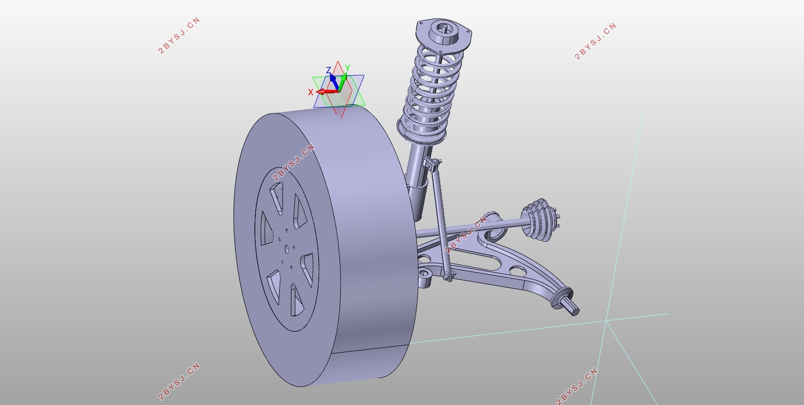
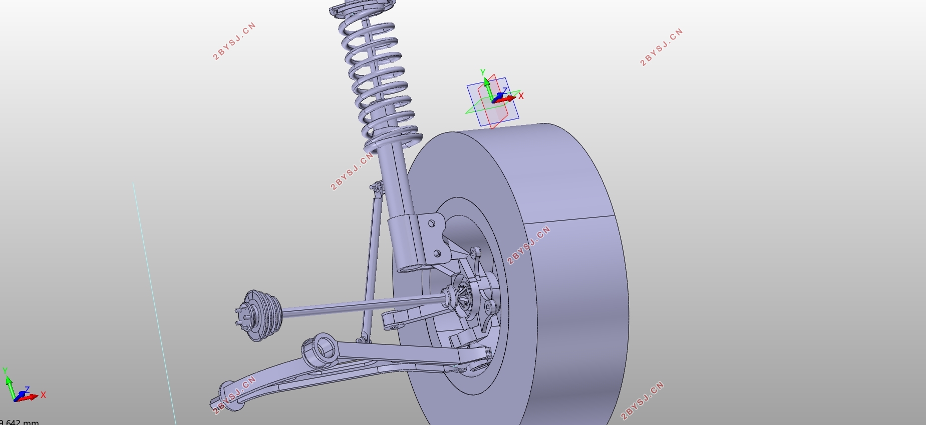
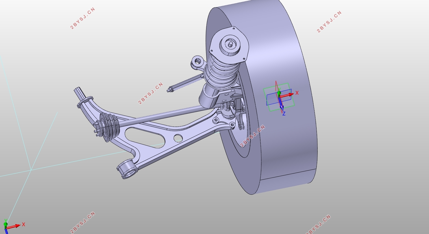
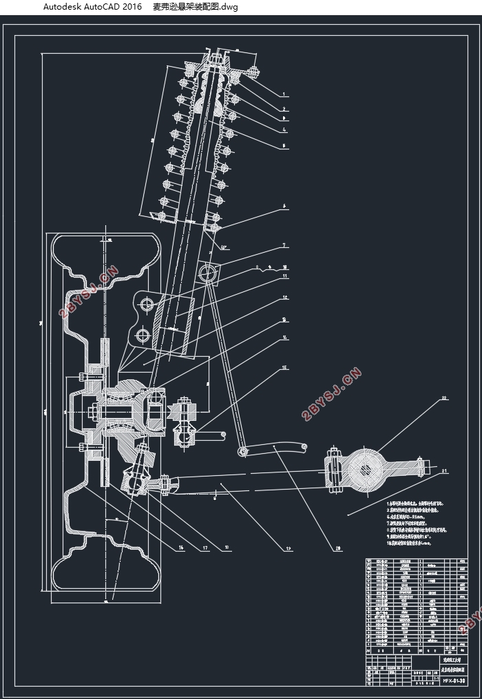
标致307轿车前麦弗逊悬架设计(含CAD零件图装配图,CATIA三维图)
无需注册登录,支付后按照提示操作即可获取该资料.
标致307轿车前麦弗逊悬架设计(含CAD零件图装配图,CATIA三维图)(任务书,开题报告,文献摘要,外文翻译,论文说明书22000字,CAD图纸7张,CATIA三维图)
摘要
为深入了解汽车悬架的设计流程,本文针对轿车的前麦弗逊悬架进行了研究。根据查询到的参考车型参数,完成悬架主要零件尺寸、性能参数选取计算,运用CATIA完成前麦弗逊悬架的虚拟样机建模,并在CATIA中提取麦弗逊悬架装配模型硬点坐标,基于本模型的硬点坐标修改Adams/Car中共享的麦弗逊悬架模型硬点坐标并进行双轮同向平行跳动仿真,剖析车轮定位参数与车轮跳动量的关系曲线。同时本文还进行了汽车经过不平路面受到瞬间冲击和制动两种工况下的车轮受力分析,应用Adams/Car的静载仿真获取两种工况下悬架下摆臂的受力情况,并在CATIA/GenerativeStructualAnalysis中进行两种工况下悬架下摆臂的有限元强度分析,从而检验本文设计模型的合理性。
关键词:麦弗逊悬架;建模;仿真;强度分析
Abstract
For depth understanding of the design process of the car suspension, this paper aims to research McPherson suspension. According to the parameters of the reference vehicle model, the main part size and performance parameters of the suspension are calculated, and the virtual prototyping of the former McPherson suspension is completed by using CATIA , then extract the Hardpoint of McPherson suspension assembly model in CATIA. The Hardpoint of the McPherson suspension model shared by Adams / Car are modified based on the hardpointof this model.This paper also analyzes the relationship between the wheel alignment parameters and the wheel runout . At the same time, this paper analyzes the wheel force of the vehicle under the condition of instantaneous impact under the uneven road surface and braking. By using the static load simulation of Adams / Car, the force of the lower arm of the suspension is obtained. The finite element strength analysis of the lower arm of the suspension is carried out in CATIA / Generative Structual Analysis, and the rationality of the design model is tested.
Key Words:Mcpherson suspension;Modeling;Simulation;Strength analysis
东风标致307车型参数[22]
名称 数值
长*宽*高 4496*1746*1536mm
轴距 2612mm
前轮距 1505mm
后轮距 1489mm
整备质量 1293kg


目录
摘要 I
Abstract II
第1章绪论 1
1.1研究背景与意义 1
1.1.1研究背景 1
1.1.2研究意义 2
1.2麦弗逊悬架研究现状 2
1.2.1国外研究现状 2
1.2.2国内研究现状 3
1.3本文主要研究内容 4
1.4本文研究的主要技术路线 4
第2章麦弗逊悬架设计计算与建模 6
2.1麦弗逊悬架介绍 6
2.2标致307轿车前麦弗逊悬架设计概述 6
2.3选取悬架主要性能参数 7
2.3.1悬架的偏频和静挠度 7
2.3.2悬架的动挠度 9
2.3.3悬架的工作行程 10
2.3.4悬架的弹性特性 10
2.3.5悬架的侧倾角刚度 11
2.4车轮定位参数的选取 11
2.4.1主销后倾角的选取 11
2.4.2主销内倾角的选取 12
2.4.3前轮外倾角的选取 13
2.4.4前轮前束的选取 14
2.4.5车轮定位参数选取小结 14
2.5弹性元件的设计计算 14
2.5.1螺旋弹簧刚度 15
2.5.2螺旋弹簧材料的选取 16
2.5.3弹簧中径和直径等几何尺寸的设计 17
2.5.4螺旋弹簧设计参数小结 18
2.5.5螺旋弹簧切应力校核 19
2.6减振器的设计 20
2.6.1减振器主要性能参数的设计 20
2.6.2减振器主要尺寸参数的设计 22
2.6.3减振器材料的选择 23
2.6.4减振器车轮托架设计 23
2.7麦弗逊悬架导向结构的设计 24
2.8横向稳定杆的设计 25
2.9本章小结 25
第3章麦弗逊悬架运动学与静载仿真分析 26
3.1利用Adams/Car模块建立麦弗逊悬架模型 26
3.2基于Adams/Car模块的麦弗逊悬架仿真分析 28
3.2.1麦弗逊悬架仿真分析前的参数修改与设置 29
3.2.2麦弗逊悬架双轮同向跳动仿真分析 31
3.2.3两种不同工况下麦弗逊悬架静载仿真分析 33
3.3本章小结 36
第4章悬架零件的强度分析 38
4.1创建下摆臂材料属性 38
4.2两种不同工况下悬架下摆臂强度分析 39
4.2.1不平路面瞬间冲击工况悬架下摆臂强度分析 39
4.2.2制动工况悬架下摆臂强度分析 41
4.3悬架下摆臂的结构优化 42
4.3.1优化后制动工况下摆臂强度分析 42
4.3.2下摆臂结构优化方案小结 43
4.4本章小结 43
第5章结论与展望 44
5.1结论 44
5.2展望 45
参考文献 46
附录A 49
致谢 50
