
微型小货车前制动器的设计(含CAD零件图装配图)
无需注册登录,支付后按照提示操作即可获取该资料.
微型小货车前制动器的设计(含CAD零件图装配图)(任务书,论文说明书10000字,CAD图7张)
摘 要
近年来世界汽车技术迅猛发展,各国政府也在大力支持发展汽车行业,从技术方面和资金方面都给了大力的支持。因为现在汽车工业的发展水平可以成为一个国家工业发展水平的标志行业。汽车作为几乎每家都有的交通出行工具,对于人们的出行和日常生活有了极大的帮助,汽车制动器作为汽车的重要安全件,是车辆安全驾驶的根本。汽车制动器可以让车辆的速度减慢,使车辆停止移动。是车辆必不可少的部件。
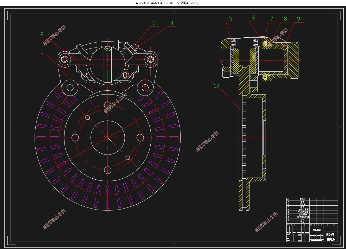
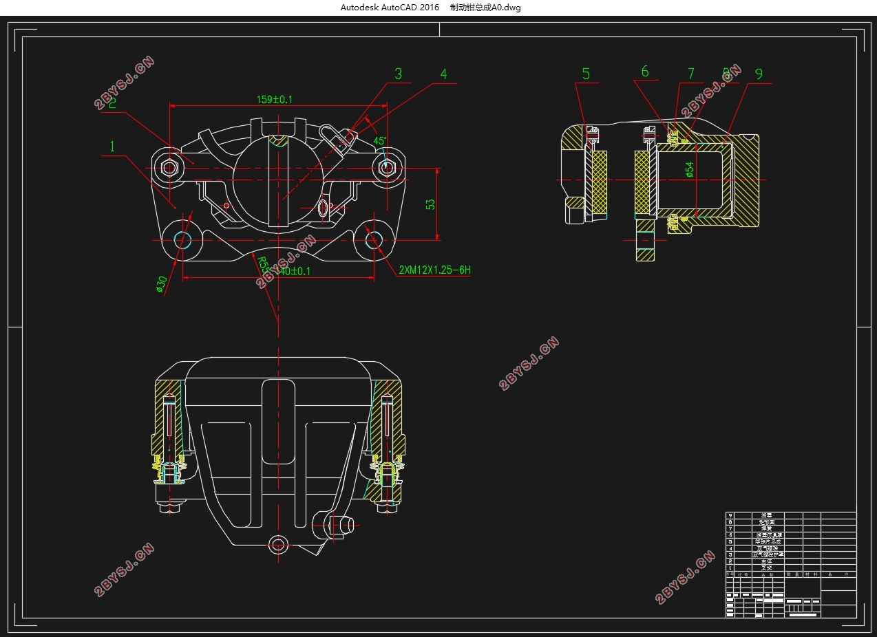
本文设计的汽车制动器,通过对现有市场上各种车型的制动器相对比,了解各制动器的结构、类型与优缺点。再根据任务书要求,根据小型货车的制动需求,制定详细的参数要求与结构类型。本文设计一种盘式制动器,分别对制动盘、制动钳、支架、衬片等零部件进行设计与计算。
关键词:盘式制动器 ,制动力,制动力分配系数,制动器因数
ABSTRACT
In recent years, the world's automotive technology has developed rapidly, and governments around the world are also vigorously supporting the development of the automotive industry, both in terms of technology and capital. Because now the development level of the automobile industry can become a sign industry of a country's industrial development level. As a means of transportation in almost every household, the car is of great help to people's travel and daily life. As an important safety part of the car, the car brake is the foundation of the safe driving of the vehicle. Car brakes slow down the vehicle and stop it from moving. It is an essential part of the vehicle.
The automobile brakes designed in this paper, through the comparison of the brakes of various models on the market, understand the structure, type, advantages and disadvantages of each brake. Then, according to the requirements of the task book, according to the braking requirements of the minivan, the detailed parameter requirements and structure types are formulated. In this paper, a disc brake is designed, and the parts such as brake disc, brake caliper, bracket and lining are designed and calculated respectively.
Key words: disc brakes, power system, power distribution coefficient system, brakefactor
2.1 设计要求
采用盘式制动器。要求对制动力、制动力分配系数、制动器因数等进行计算。对制动器主要零件,如制动鼓、制动蹄、摩擦衬片(衬块)进行结构设计和设计计算。
2.2 整车参数
车型:五菱
基本参数:
1)轴距:L=2350mm;
2)最高车速:Vmax=105 Km/h;
3)汽车空载质量:ma =985Kg; 汽车满载总质量:ma =1620Kg;
4)空载时汽车的质心高度:hg =800mm; 满载时汽车的质心高度为hg=930mm;
5)汽车空载时的轴荷分配:前轴60%,后轴40%;
汽车满载时的轴荷分配:前轴52%,后轴48%;
6)汽车空载时质心到前后轴的距离:L1= L*0.40=2350*0.40=940mm;
L2= L*0.60=2350*0.60=1410mm;
汽车满载时质心到前后轴的距离:L1=L*0.52=2350*0.52=1222mm;
L2=L*0.40=2350*0.48=1128mm;
7)车轮有效半径re
选用80系列轮胎,查阅GB/2978, 155/80R13 新胎滚动半径为281mm, 得有效半径为Re=281mm。

目 录
摘 要 1
ABSTRACT 2
第1章 绪论 4
1.1 引言 4
1.2 国内外发展趋势 4
1.3 本文设计目标 4
第2章 制动器的设计计算 5
2.1 设计要求 5
2.2 整车参数 5
2.3 受力分析 5
2.4 同步附着系数的确定及计算 8
2.5 制动力、制动强度、附着系数利用率的计算 11
2.5.1满载时的情况 11
2.5.2 空载的情况 12
2.6 制动器最大制动力矩的计算 14
2.7 主要零部件的结构设计 14
2.7.1制动盘 15
3.7.2制动块 15
2.7.3制动钳 16
2.8 制动器因数及制动距离的计算 17
2.8.1制动器因数的计算 17
2.8.2制动器距离的计算 18
2.9 校核计算 18
2.9.1 摩擦衬块的磨损特性计算 18
2.9.3 盘式制动器制动力矩的校核 20
2.10 驻车制动计算 23
2.11 计算结果 24
总结 25
致 谢 26
参考文献 27