超声雾化系统的设计(含CAD图)
无需注册登录,支付后按照提示操作即可获取该资料.
超声雾化系统的设计(含CAD图)(任务书,开题报告,论文说明书19000字,CAD图纸6张)
摘 要
由于超声波雾化具有雾滴细小、雾滴大小分布均匀、液体输送压力小、喷雾过程无堵塞和功率损耗小等特点,在日常生活、农业、医学和工业等各个领域得到了广泛的应用。根据超声雾化喷头的工作频率进行划分,可以分为低频(20~100kHz)超声雾化喷头和高频(大于1MHz)超声雾化喷头。由于低频超声雾化喷头可靠性更高,对雾化液的要求较低,可雾化的液体粘度更高,其雾化量相对也较大等优点,其应用范围比高频超声雾化喷头更广泛。但是,目前低频超声雾化喷头还普遍存在一些问题,如体积较大、结构不紧凑和雾滴分布不均匀等问题,因此,本文设计一种体积小、结构紧凑以及雾滴分布均匀的低频超声雾化喷头,设计频率为65kHz。论文主要通过理论计算、Abaqus有限元仿真分析和实验测试进行设计超声雾化喷头,主要内容如下:
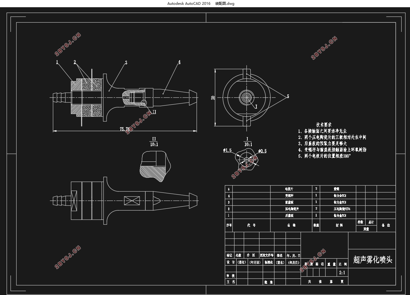
(1)通过理论计算,设计了超声雾化喷头的结构。换能器将螺杆和前盖板做成一体,后盖板做成锁紧螺母,使换能器的结构更加紧凑。同时,换能器的前盖板做成前小后大的形状,使换能器同时具有振幅放大的作用。变幅杆采用圆锥形,雾化小端做成蘑菇形,可以提高超声雾化的效果。
(2)通过Abaqus的模态仿真分析,喷头的谐振频率为62.811kHz。为了得到频率偏差更小的喷头,通过减小纵向尺寸对喷头进行优化设计,最终设计谐振频率为64.231kHz。
(3)通过谐响应分析,验证了超声雾化喷头在谐振频率附近振幅最大,并分析了喷头的应力分布。
(4)利用IM3570型阻抗分析仪对超声雾化喷头进行阻抗测试实验得到其实际谐振频率为63.824kHz,与设计频率相差1.81%。对超声雾化喷头进行喷雾实验,喷雾均匀,有效功耗低,雾化性能良好。在有效功耗为1W时,最大雾化流量为10mL/min。
关键词:超声雾化;换能器;变幅杆;谐振频率;有限元法
Abstract
Since the ultrasonic atomization droplet having a fine, uniform droplet size distribution, fluid delivery pressure is small, the spray process without clogging and loss of power and other characteristics, in all areas of daily life, agriculture, medicine and industry have been widely used. According to the operating frequency, ultrasonic atomizer can be divided into low frequency (20 ~100kHz) and high-frequency (more than 1MHz) ultrasonic atomizer. Because the low-frequency ultrasonic atomizer has higher reliability, lower requirement for liquid atomization and higher viscosity of the liquid can be atomized, larger flow rate and so on, the range of applications of low frequency ultrasonic atomizer is bigger than high-frequency ultrasonic atomizer. However, at present the low-frequency ultrasonic atomizer is generally has some problems, such as large size, uncompact structure, uneven distribution of droplets, and so on. Therefore, this time I’m to design a ultrasonic atomizer which has a small size , compact structure and it’s distribution of droplets are uniform, and it’s frequency is 65kHz.
Thesis mainly through the theoretical calculation, using Abaqus finite element simulation analysis and experimental test to design a ultrasonic atomizer and it’s frequency is 65 kHz.
(1)The structure of ultrasonic atomizer is designed by theoretical calculation. The screw and the front cover is formed integrally, rear cover is made as a fasten the screw nut, so the structure of the transducer are more compact. At the same time, the transducer front cover is made to be one end is small and the other end is big, so the transducer can enlarge amplitude. The amplitude is made by a cone, and the front of the amplitude is made as a mushroom so as to increase the effect of ultrasonic atomization.
(2)The resonant frequency of the ultrasonic atomizer is 62.811kHz by Abaqus’s modal simulation analysis. In order to reduce the deviation of design, making a optimal design by reduce the length of the ultrasonic atomizer, and the final frequency is 64.231kHz.
(3)It’s verified that the largest amplitude is near the resonance frequency of the ultrasonic atomizer by harmonic response analysis, stress distribution also was analyzed, too.
(4)The resonant frequency of the ultrasonic atomizer is 63.824kHz tested by impedance analyzer IM3570, and the deviation is 1.81% compared with the design frequency. A spray experiment was did for the ultrasonic atomizer, the result shows that the dropets is uniform and the effective power consumption is low, the atomization performance is good. The biggest liquid flow rate is 10mL/min when the effective power consumption is 1W.
Key Words:ultrasonic atomization; transducer; the amplitude; resonant frequency; finite element methods


目 录
第1章 绪论 1
1.1 研究目的及意义 1
1.2 国内外研究现状 1
1.3 本章小结 5
第2章 超声雾化喷头设计 6
2.1 超声雾化原理 6
2.2 超声雾化喷头结构 6
2.3 换能器的理论分析及计算 6
2.3.1 换能器的选择 6
2.3.2 换能器的结构设计 7
2.3.3 换能器的材料选择 9
2.3.4 换能器的尺寸计算 11
2.4 变幅杆的设计 12
2.4.1 变幅杆的选择 12
2.4.2 变幅杆的尺寸计算 12
2.5 本章小结 13
第3章 模态仿真分析与优化设计 14
3.1 模态仿真的目的 14
3.2 模态仿真的原理 14
3.3 模态仿真 14
3.3.1 有限元模型的建立 14
3.3.2 模态仿真过程 15
3.3.3 模态仿真结果分析 17
3.4 优化设计 18
3.5 本章小结 18
第4章 谐响应仿真分析 19
4.1 谐响应仿真的目的 19
4.2 谐响应仿真的原理 19
4.3 谐响应仿真 19
4.3.1 谐响应仿真过程 19
4.3.2 谐响应仿真结果分析 20
4.4 本章小结 22
第5章 实验测试 23
5.1 阻抗测试实验 23
5.1.1 阻抗测试实验原理 23
5.1.2 阻抗测试实验分析 24
5.2 喷雾实验 25
5.3 本章小结 27
第6章 总结与展望 28
6.1 完成的主要工作和结果 28
6.2 进一步的研究与展望 28
参考文献 30
致 谢 32
