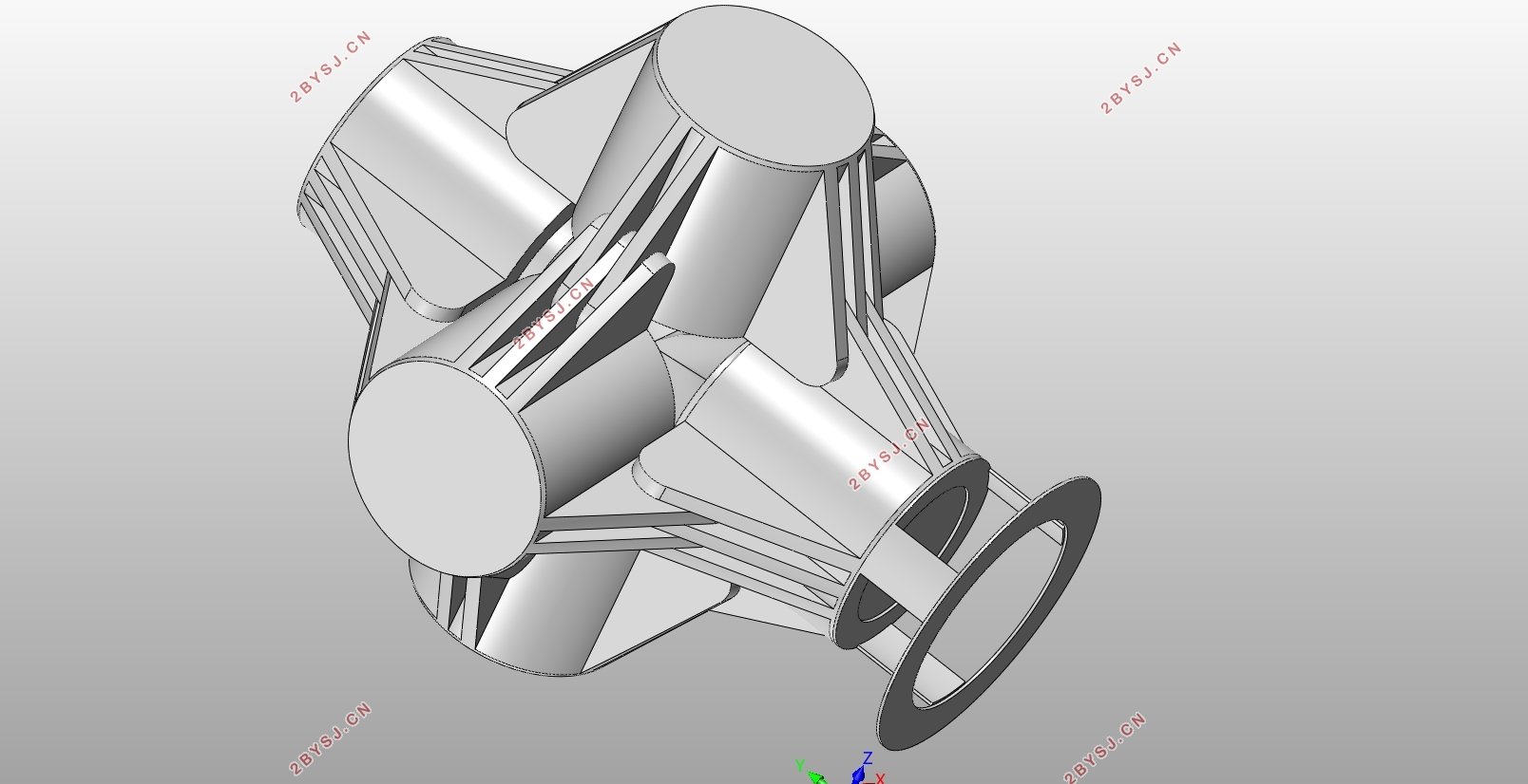
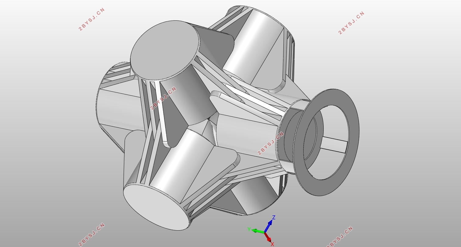
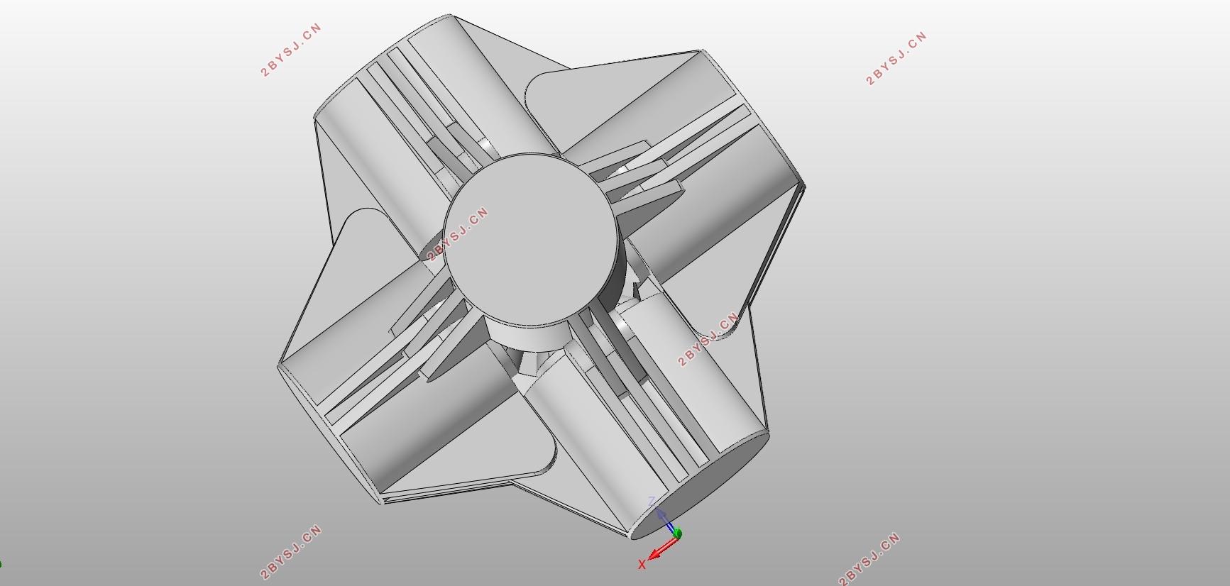
金刚石六面顶压机的设计(含CAD零件图装配图,SolidWorks三维图)
无需注册登录,支付后按照提示操作即可获取该资料.
金刚石六面顶压机的设计(含CAD零件图装配图,SolidWorks三维图)(论文说明书23000字,CAD图5张,SolidWorks三维图)
摘要
六面顶压机是一种超高压的压缩设备,一般用于合成人工金刚石等超硬质材料等用途。根据设备结构区分,有着铸造梁式六面顶压机和铰接梁式六面顶压机。相比铸造梁式的顶压机,铰接梁式顶压机有着精度稳定性高、使用寿命长,设备稳定性好等特点。
本文的工程背景是来自河南省揭榜挂帅的重点项目。因为根据行业内普遍采用的铸造缸梁六面顶压机是无法很好的满足更大型化的工艺要求的。而且设备的材料性能稳定性较差、抗疲劳寿命短、精度稳定性不够等困难。所以我们需要研究锻造结构的金刚石压机铰接梁的作业精度。
本文的主要设计内容是对铰接式六面顶压机的设计,和顶压机装配精度影响因素的研究与单元结构精度的分析。
关键词:六面顶压机、精度、铰接式
ABSTRACT
The six-sided top press is a kind of ultra-high pressure compression equipment, which is generally used for synthesizing artificial diamond and other ultra-hard materials. According to the equipment structure, there are cast beam type six-sided top press and hinged beam six-sided top press. Compared with the cast beam type top press, the hinged beam type top press has the characteristics of high precision and stability, long service life and good equipment stability. The engineering background of this paper is a key project from Henan Province. Because the cast cylinder beam six-sided top press commonly used in the industry cannot well meet the larger-scale process requirements. Moreover, the material performance stability of the equipment is poor, the fatigue life is short, and the accuracy and stability are not enough. Therefore, we need to study the working accuracy of the hinged beam of the diamond press for forging structures. The main design content of this paper is the design of the articulated six-sided top press, the research on the influencing factors of the assembly accuracy of the top press and the analysis of the unit structure accuracy.
Key words: six-sided top press, precision, articulated type
设计要求
DJ850的其主要的技术参数包含:
(1)单缸推力可达到:62MN
(2)系统压力:14MPa
(3)额定设定压力:110MPa
(4)活塞行程:100mm
对于整体的循环工作的速度设定主要包括:快速下降、慢速下降、停留、快速上升。但从系统的实际设计用途和经济性能上看,也可以很明显的看出系统对回路循环运动速度的控制精度和应用经济性能的要求并不高,所以在进行设计和加工挑选循环调速控制回路时,还应在尽量满足其精度控制要求的情况下,考虑其成本的控制。


目录
第一章绪论 3
1.1 引言 3
1.2 国内外发展现状 3
1.3 技术经济型分析 4
第二章总体方案设计 5
2.1 设计要求 5
2.2设计方案选择 5
2.3校正压装机液压系统负载和工况图分析 5
2.3.1设计校正压装机液压系统工况图分析 5
2.3.2工作负载 6
2.3.3惯性负载 6
2.3.4负载图和速度图的绘制 7
2.4液压系统回路图的拟 7
2.4.1选择供油方式 7
2.4.2选择换向回路 8
2.4.3安全保障和速度控制回路 8
2.4.4组成液压系统回路图 9
第三章液压元件的选型 11
3.1油缸主参数的确定 11
3.1.1 液压缸的内径 11
3.1.2 活塞杆的直径 12
3.1.3液压缸缸体厚度计算 14
3.1.4 液压缸长度的确定 16
3.1.5 缸筒的加工要求 17
3.1.6法兰设计 17
3.1.7 (缸筒端部)法兰连接螺栓的强度计算 17
3.2 活塞的设计 19
3.3 导向套的设计与计算 19
3.4 端盖和缸底的设计与计算 20
3.5 缸体长度的确定 21
3.6 缓冲装置的设计 21
3.7 排气装置 21
3.8 密封件的选用 24
3.9 防尘圈 25
3.10 液压泵和电动机数据计算及选型 25
3.11液压缸工作压力和尺寸的计算 26
3.11.1初选液压缸工作压力 26
3.12.2液压缸尺寸的计算 26
3.12选择阀类元件及其他辅助元件的选型 26
3.12.1单向阀 26
3.12.2调速阀 27
3.12.3顺序阀 27
第四章液压系统的性能验算 29
4.1压力损失及调定压力的确定 29
4.1.1沿程压力损失 29
4.1.2局部压力损失 29
4.1.3总的压力损失 30
4.1.4压力阀的调定值 30
4.2系统的发热和温升 30
第五章误差分析与精度分析 31
5.1 振动基础理论 31
5.2 连续系统自由振动 31
5.3 ansys有限元软件简介 33
5.4 ansys自由模态分析的基本操作 34
5.5 约束下缸的模态分析 39
5.6精度分析 45
第六章三维建模与虚拟装配 49
6.1 零件建模 49
5.1.1顶压机支座建模 50
5.1.2顶缸建模 51
6.2 装配体命令 51
总结 53
致谢 54
参考文献 55
