单缸气动楔式闸阀的设计(含CAD零件图装配图)
无需注册登录,支付后按照提示操作即可获取该资料.
单缸气动楔式闸阀的设计(含CAD零件图装配图)(论文说明书16000字,CAD图7张)
摘 要
阀门是石油、化工、电站、长输管线、造纸、核工业、各种低温工程、宇航以及海洋采油等流体输送系统中的控制部件,具有导流,截止,调节,节流,防止逆流,分流或溢流卸压等功能。阀门通常由阀体、阀盖、阀座、启闭件、驱动机构、密封件和紧固件等组成。阀门的控制功能是依靠驱动机构或流体驱使启闭件升降、滑移、旋摆或回转运动以改变流道面积的大小来实现的。阀门根据其种类和用途有不同的要求,主要有密封、强度、调节、流通、启闭等性能。在设计和选用阀门时,除了要考虑基本参数和性能外,还要考虑流体的性能,包括流体的相态、腐蚀性、粘度、毒性、易燃易爆性和放射性等。
闸阀是指关闭件(闸板)沿通路中心线的垂直方向移动的阀门,是利用闸板和阀座来控制启闭的阀门。闸阀主要由阀体、阀座、闸板、阀杆、阀盖、填料函、填料压盖、阀杆螺母、手轮等构成。闸板与阀座间相对位置的改变,即可改变通道大小又可截断通道。此次设计是针对单缸气动楔式闸阀进行设计,主要介绍了闸阀的结构特点和手动—气动转换装置的特点,以及其工作原理。阀门设计包括很多内容,首先对阀门的工作条件及其基本技术参数进行确定,从而选择阀体材料、阀体结构形式,确定密封副的结构和尺寸这是关键。然后进行阀门主要通用零件的设计计算,这部分主要包括以下几部分内容:
(1)阀体壁厚的计算、
(2)阀体中法兰的设计与计算、
(3)闸板的设计与计算、
(4)阀盖装置的设计与计算、
(5)填料装置的设计与计算、
(6)阀杆的设计与计算、
(7)气缸的设计与计算等。
其次,对设计的部件和零件进行受力分析,根据国家标准和推荐尺寸来确定实际尺寸,然后进行强度校核。最后,利用计算机绘图软件(CAD)绘制总装图和零件图,完成本次设计。
关键词:阀门 手动—气动转换 密封面 楔式闸阀
Abstract
Valve is oil, chemical, power plant, long pipeline, paper, nuclear industry, a variety of low-temperature engineering, aerospace and offshore oil recovery. The control parts of the fluid conveying system have the diversion, the cut-off, the adjustment, the throttling, the prevention of the backflow, the diversion or the relief of the overflow And other functions. Valve usually by valve, valve cover, valve seat, open and close parts, drive mechanism, seals and fasteners and other components. Valve The control function of the door depends on the size of the driving mechanism or fluid that drives the hoist, slide, swing or rotary movement to change the area of the runner. Valve according to its type and purpose have different requirements, the main sealing, strength, adjustment, circulation, opening and closing performance. In the design and selection of valves, in addition to considering the basic parameters and performance, but also consider the fluid properties, including fluid phase state, corrosive, viscosity, toxic, flammable and explosive and radioactivity.
Gate valve is the valve closed (gate) along the centerline of the central line of the vertical direction of the valve, is the use of the gate and the valve seat to control the opening and closing of the valve. The valve is mainly composed of a valve body, a valve seat, a valve board, a valve rod, a valve cover, a stuffing box, a packing gland, a valve rod nut, a hand wheel, etc.. The change of relative position between the gate and the valve seat can change the channel size and the truncated channel. This design is designed for single cylinder pneumatic wedge type gate valve, mainly introduces the structural characteristics of the valve and manual gas conversion device characteristics, and its working principle. Valve design includes a lot of contents, first on the valve working conditions and the basic technical parameters are determined, to choose the material of valve body, a valve body structure determined sealing pair structure and size is the key. Then the main common parts of the design and calculation of the main parts, this part mainly includes the following parts:(1) calculation of the wall thickness of the valve body、(2) design and calculation of flange in valve body、(3) design and calculation of the gate、(4) design and calculation of valve cover、(5) the design and calculation of the stuffing device、(6) design and calculation of the valve stem、7) the design and calculation of the cylinder. Secondly, the design of the components and parts subjected to force analysis, according to national standards and recommended size to determine the actual size, and then intensity verification. Finally, the design of this design is accomplished by drawing the assembly and drawing of the parts using computer graphics (CAD)..
Keywords: Valve;The hand pneumatic change;Seal;Dyadic valve of wedge
工作原理
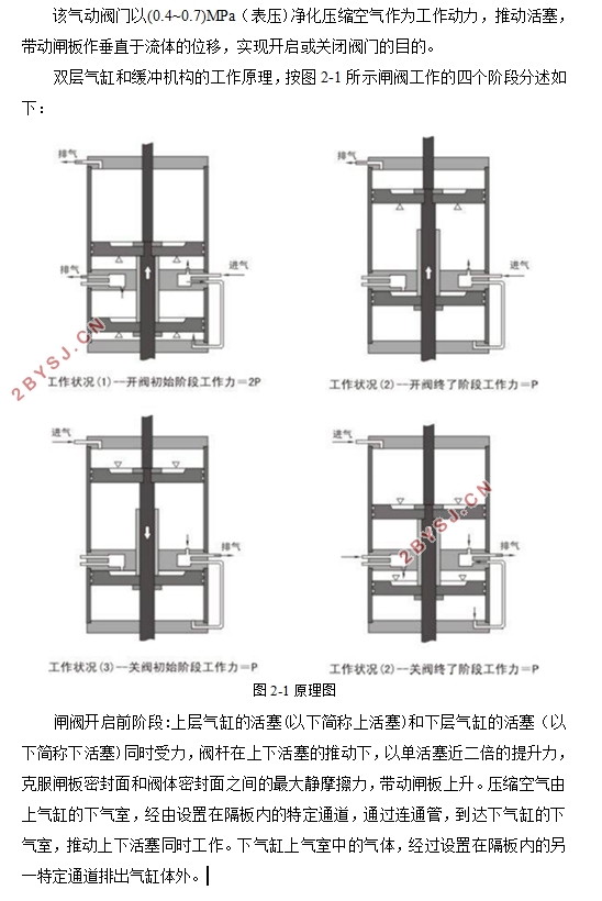
该气动阀门以(0.4~0.7)MPa(表压)净化压缩空气作为工作动力,推动活塞,带动闸板作垂直于流体的位移,实现开启或关闭阀门的目的。


目录
摘要 I
Abstract II
第一章 绪论 1
1.1选题意义 1
1.2国内外阀门的发展 2
1.2.1国外阀门的发展 2
1.2.2国内阀门的发展 2
1.3 闸阀的介绍 3
1.3.1闸阀工作原理和结构 3
1.3.2闸阀的优缺点 4
第二章 气动—手动楔式闸阀的介绍 5
2.1工作原理 5
2.2气动闸阀的结构特点 6
第三章 主要部件的设计与计算 8
3.1阀体的设计与计算 8
3.1.1阀体的功能 8
3.1.2阀体的选材 8
3.1.3阀体的结构形式和制造方法 9
3.1.4确定阀体的结构长度和连接尺寸 9
3.1.5阀座结构设计与计算 10
3.1.6阀体壁厚的设计与计算 11
3.1.7中法兰的设计与计算 12
3.2闸板的设计与计算 16
3.2.1闸板密封面宽度和内径的选取 16
3.2.2闸板与阀体裆宽及相应公差的计算 17
3.2.3闸板主要结构尺寸的确定 18
3.2.4闸板密封面比压计算 19
3.2.5 闸板强度的校核 19
3.3阀杆的设计与计算 20
3.3.1阀杆总轴向力 20
3.3.2阀杆直径的估算 21
3.3.3阀杆的强度校核 21
3.3.4阀杆的稳定性校核 23
3.3.5阀杆主要尺寸得确定 25
3.4阀盖及填料装置的设计与计算 26
3.4.1阀盖的设计与计算 26
3.4.2填料压盖的设计与计算 28
3.4.3活节螺栓的设计与校核 32
3.4.4销的设计与校核 33
3.4.5上密封座尺寸 33
3.5气缸的设计与计算 34
3.5.1气缸直径的估算与设计 34
3.5.2气缸的校核 34
第四章 其它主要零件的设计与校核 36
4.1滚动轴承的选取 36
4.2手轮直径的确定 36
4.3阀杆螺母的校核 37
结论与展望 39
参考文献 41
致谢 43
