
EQ1092F8AD型长头柴油载货汽车转向系统设计(含CAD图)
无需注册登录,支付后按照提示操作即可获取该资料.
EQ1092F8AD型长头柴油载货汽车转向系统设计(含CAD图)(任务书,开题报告,外文翻译,文献摘要,论文说明书13000字,CAD图7张)
摘要
当汽车在路面的前进过程中,要求多次依靠驾驶员的想法来调整汽车的前进方向,以上便是汽车转向的定义。汽车的转向系统在本质上是一套机械机构,是用来实现汽车方向的改变。本次设计的研究内容是EQ1092F8AD型长头轻型货车的转向系设计。
本文的主要的任务是设计一套整体式转向机构,并且其能够适用于本设计中轻型货车的悬架类型。我们根据汽车设计以及相关的连杆机构的知识,我们首先选择了转向器的形式,随后再选择了转向传动机构,对转向梯形的形式进行选择。随后对转向器的各部分进行设计计算,比如其中的齿扇,螺母,齿条以及螺杆等。在转向梯形中计算梯形臂和底角。最后利用CATIA软件完成转向系统的三维模型设计,并将各部分装配起来。
在本次设计中,考虑到货车的工作状况以及前轴载荷的,为此转向器选择了循环球式-齿条齿扇转向器。在该型转向器的设计中,其中包含了螺母-钢球-螺杆传动副和齿条-齿扇传动副的设计。螺母-钢球-螺杆传动副的设计首先根据前轴载荷确定齿扇模数,再查表确定钢球直径,钢球中心距以及螺杆外径等其他一系列尺寸。齿条-齿扇传动副的设计也是首先根据前轴载荷来确定齿扇模数,再选择压力角和齿扇宽等一系列尺寸。
本次设计中转向梯形采用的是整体式转向梯形。在本次设计中,我们首先根据转向梯形的结构要求及性能要求建立约束条件,大概计算出梯形臂的长度区间以及梯形底角的区间范围。再建立相应的优化模型,选择不同的梯形臂长和梯形底角进行仿真,最后选择误差最小的一组。
本文在参考了相关资料后,归纳出了一套轻型货车转向系统的设计步骤及具体方法,为后人解决相关问题提供了清晰的思路。
关键词:转向系;转向器;传动副;转向传动机构;转向梯形。
ABSTRACT
When a car is moving forward on the road, it is required to rely on the driver's ideas to adjust the direction of the car for many times. This is the definition of car steering. The steering system of automobile is essentially a set of mechanical mechanism, which is used to change the direction of automobile. The research content of this design is the steering system design of EQ1092F8AD long-head light truck.
The main task of this paper is to design a set of integral steering mechanism, and it can be applied to the suspension type of light truck in this design. According to the knowledge of automobile design and related connecting rod mechanism, we first choose the form of steering gear, then choose the steering transmission mechanism to select the form of steering trapezium. Subsequently, the design calculation of each part of the steering gear, such as the gear fan, nut, rack and screw, is carried out. The trapezoidal arm and bottom angle are calculated in the steering trapezoid. Finally, the three-dimensional model of steering system is designed with CATIA software, and all parts are assembled.
In this design, considering the working condition of the truck and the load of the front axle, the circular spherical rack fan steering gear is chosen for the steering gear. In the design of this type of steering gear, it includes the design of nut-ball-screw transmission pair and rack-fan transmission pair. The design of nut-ball-screw transmission pair first determines the module of gear sector according to the front axle load, and then determines a series of other dimensions such as ball diameter, ball center distance and screw outer diameter by looking up tables. The design of rack-gear fan transmission pair is also based on the front axle load to determine the modulus of the gear sector, and then select a series of dimensions such as pressure angle and width of the gear sector.
In this design, the steering trapezoids are integral steering trapezoids. In this design, we first establish constraints according to the structural and performance requirements of the steering trapezoid, and roughly calculate the length range of the trapezoid arm and the bottom angle range of the trapezoid. Then the corresponding optimization model is established, and different trapezoidal arm lengths and trapezoidal bottom angles are selected for simulation. Finally, the group with the least error is selected.
After referring to the relevant information, this paper sums up a set of design steps and specific methods of light truck steering system, which provides a clear idea for future generations to solve related problems.
Key words:steering system; steering gear; steering trapezoid; transmission pair; structural elements
4.1转向传动机构的选择
在转向器和转向节之间存在一系列杆件,它们的总称为转向传动机构。其主要功能是将转向器输出的力和运动传递到转向节,以便实现车轮的转动,并且可以让两转向轮按照一定的角度关系偏转。
鉴于本次设计的是EQ1092F8AD型长头货车转向系设计,因此选择特殊的非独立式悬架所配用的转向传动机构。
4.2整体式转向梯形相配的转向传动机构
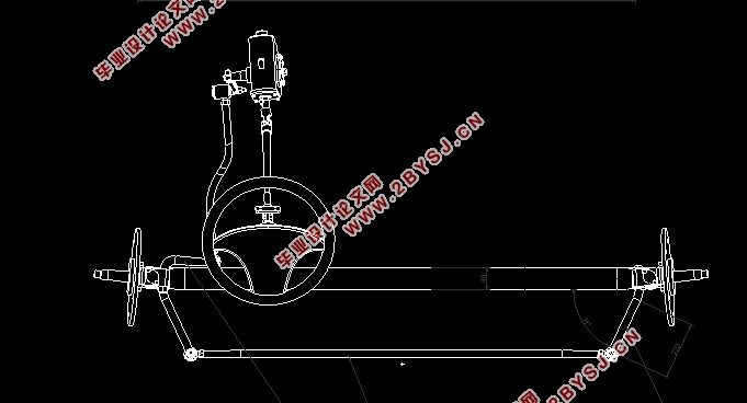
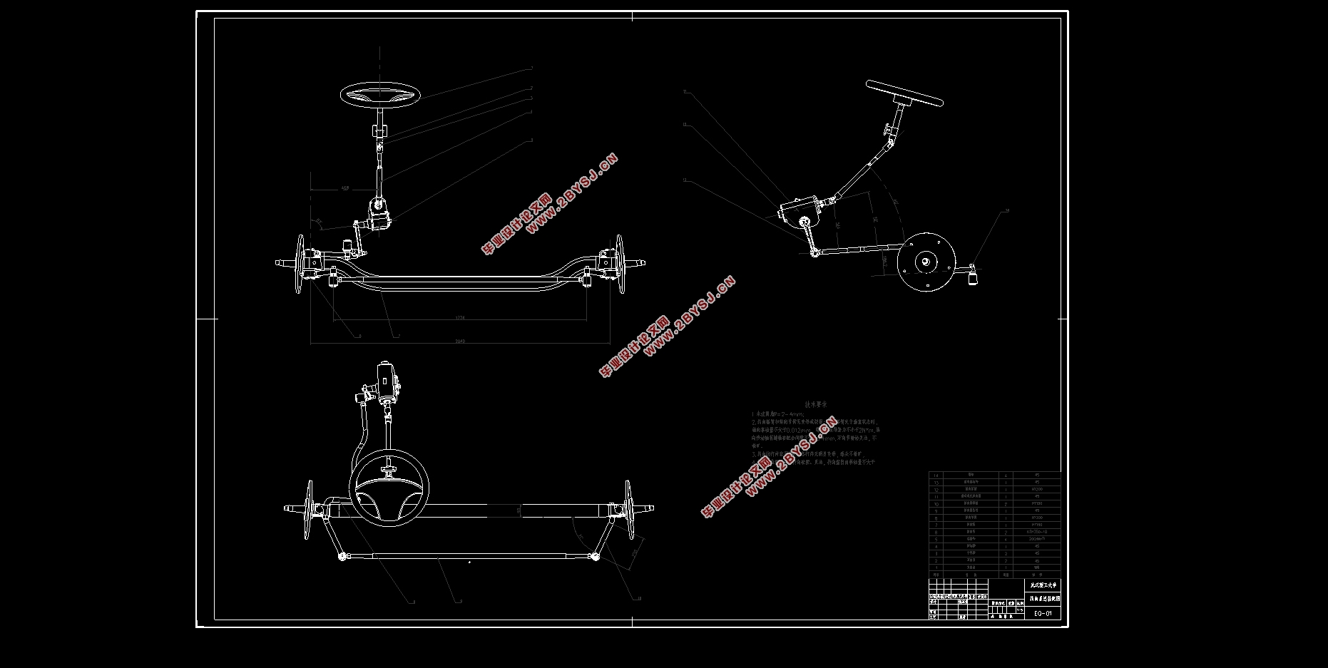
转向传动机构由转向摇臂、转向直拉杆、转向节臂和转向梯形等组成,其中转向梯形由梯形臂、转向横拉杆和前轴组成,如图4-1所示。

目录
第1章绪论 1
1.1 转向系概述 1
1.2 目的和意义 1
1.3国内外研究现状 1
1.4EQ1092F8AD型长头轻型货车转向系设计的主要内容 2
第2章汽车转向系方案 3
2.1转向系的主要性能参数 3
2.1.1转向器的传动效率 3
2.1.2 传动比的变化特性 5
2.1.3 转向盘的总转动圈数 6
2.2 转向系的选择 7
2.2.1 机械式转向系 7
第3章转向器方案的选择 9
3.1机械式转向器的选择 9
3.1.1 循环球-齿条齿扇式转向器 9
第4章汽车转向传动机构 11
4.1转向传动机构的选择 11
4.2整体式转向梯形相配的转向传动机构 11
4.3转向梯形的选择 13
第5章转向系的设计计算 14
5.1方向盘直径的选取 14
5.2转向器类型选择及其设计计算 14
5.2.1 螺杆-钢球-螺母传动副设计 14
5.3齿条-齿扇传动副设计 17
5.4转向器的计算和校核 20
5.4.1 循环球式转向器零件的强度计算 20
5.4.2齿的弯曲应力 21
5.4.3钢珠与滚道之间的接触压力 22
5.4.4转向摇臂的轴径确定 23
5.5整体式转向梯形的优化 23
第6章基于Matlab的转向梯形机构优化设计 27
6.1建立相应的主函数 27
6.2 生成实际值和期望值图像及相应函数 29
结论 33
参考文献 34
致谢 35