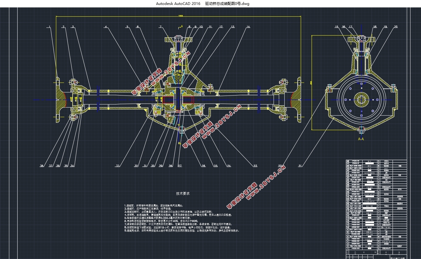
五菱宏光驱动桥设计(含CAD零件图装配图,SolidWorks三维图)
无需注册登录,支付后按照提示操作即可获取该资料.
五菱宏光驱动桥设计(含CAD零件图装配图,SolidWorks三维图)(任务书,开题报告,外文翻译,论文说明书10000字,CAD图6张,SolidWorks三维图)
摘 要
一辆汽车在路上行驶,它的发动机转速最高可以到达3000转每分钟,而要使其转速在短时间内达到这样一个速度,其变速齿轮必须得具有很大的传动比。而当传动比较大时会造成一定的设计困难,很容易想到,齿轮传动比变大,齿轮半径也会随之增大,齿轮半径变大,装载齿轮的变速箱的尺寸也会变大,如此会使汽车内部的各零件的空间非常狭小。而在降低转速的同时,传动的扭矩必然增大,内部的传负荷会随扭矩的增大而线性增加,在解决这个麻烦上,主减速器有着不可替代的作用和地位。
我们通过书本可以知道主减速器有两大作用:一个是可以随意的改变汽车各个位置的的传动比,另一个就是能够改变力的作用方向。这样就可以有效的解决上面的问题,我们知道变速器的输出就是一个纵向轴线的转矩旋转,这个时候为了将动力传输到车桥的车轮上面,就必然得有一个改变汽车动力方向的装置,而内部传负荷增大时也需要一个能够调节改变传动比的装置来缓解汽车内部的负荷,主减速器改变传动比之后,汽车对于传输能力的要求就会有所减轻,于是有效的减小了传输的大小,使车辆的布置格局更加合理。
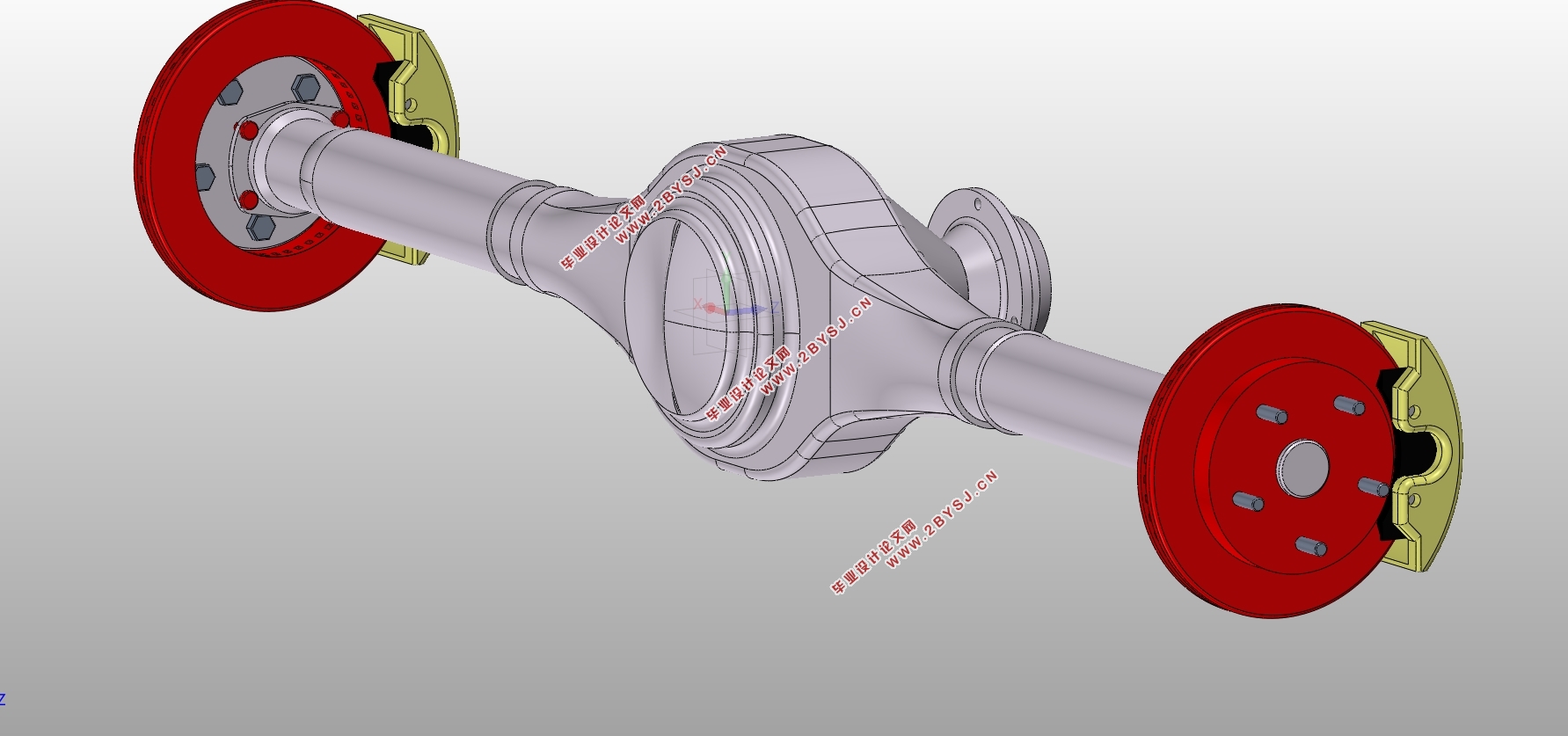
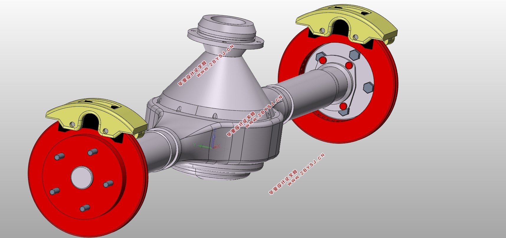
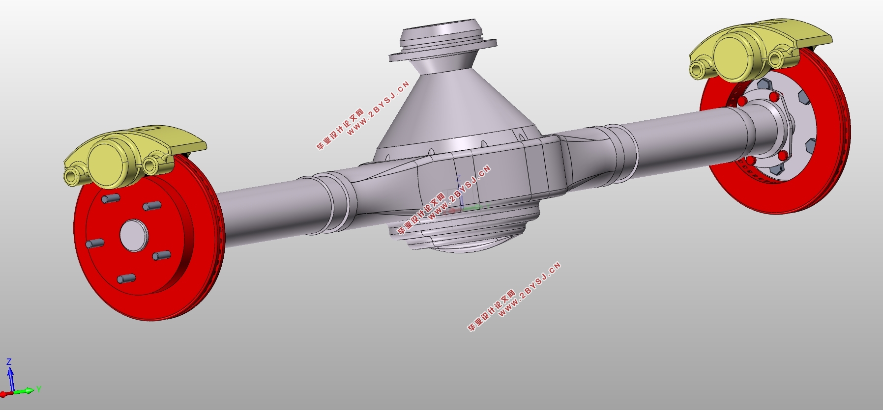
本次设计拟用设计车型为五菱宏光微型客车,设计驱动桥。该车的驱动桥通过查阅相关资料可以了解到其减速器具有体积小,质量小,结构简单的特点。而在制造起来也很简单,所以在很多车上都有应用,一般普遍应用在中小型汽车之中。
关键词:主减速器;主动齿轮;从动齿轮;
ABSTRACT
A car runs on the road, and its engine can reach up to 3000 revolutions per minute, and to make its speed reach such a speed in a short time, the gear must have a large transmission ratio. And when the transmission is relatively large, it will cause certain design difficulties. It is easy to think that the gear ratio becomes larger, the radius of the gear will increase, the radius of the gear becomes larger, the size of the gearbox loading gear will become larger, so that the space of the parts of the car will be very narrow. While reducing the speed, the torque of the transmission will inevitably increase, and the internal load will increase linearly with the increase of torque. In solving this problem, the main reducer has an irreplaceable role and status.
We know through books that the main decelerator has two major functions: one is the drive ratio that can change the car's position at random, and the other is the direction that can change the force. This can effectively solve the above problem. We know that the output of the transmission is the torque rotation of a longitudinal axis. This time, in order to transfer the power to the wheel of the axle, it is necessary to have a device to change the direction of the car's power, and the internal load will also need to be adjusted. The transmission ratio is used to alleviate the internal load of the car. After the main reducer changes the transmission ratio, the requirement of the transmission capacity will be reduced, so the size of the transmission is reduced and the layout of the vehicle is more reasonable.
This design is designed to use the Wuling Hongguang minibus and design the driving axle. The driving axle of the vehicle can learn from its relevant data that its reducer has the characteristics of small volume, small quality and simple structure. It is also very simple in manufacturing, so it has applications in many cars, and is generally used in small and medium-sized cars.
Key Words: final drive;final drive ratio;driving gear;driven gear

目录
摘 要 1
ABSTRACT 2
第1章 绪论 1
1.1 驱动桥的种类和结构 1
1.1.1 汽车车桥的种类 1
1.1.2 驱动桥的结构 1
1.2 设计内容 1
第2章 主减速器方案选取 3
2.1 主减速器形式 3
2.1.1 主减速器齿轮传动类型 3
2.1.2 主减速器减速方案的选取 4
2.1.3 齿轮的支承方式 5
2.2 主减速器各项参数计算 7
2.2.1 主减速器承载压力 7
2.2.2 齿轮主要数据 9
2.2.3 主从动齿轮的材质选择及其加热处理 10
2.2.4 轴承的载荷计算 10
第3章 差速器设计 15
3.1 差速器的结构形式选择 15
3.2 差速器的结构 16
3.3 差速器的设计 17
3.3.1 差速器齿轮的基本参数的选择 17
3.3.2 几何参数计算 19
3.3.3 强度计算 20
第4章 驱动半轴结构方案选择及计算 21
4.1 半轴的种类及特点 21
4.3 半轴杆直径的计算 23
4.4 半轴的强度及其计算 23
4.5 半轴花键的计算 24
4.5.1 花键尺寸参数的计算 24
4.5.2 花键的校核 25
第5章.汽车驱动桥外壳的设计计算 27
5.1车轴力分析和强度计算 27
5.1.1 当车辆以最大牵引力行驶时轴壳强度的计算 27
5.1.2 计算最大侧向力下的轴壳强度 28
5.1.3 不均匀道路冲击荷载下轴壳强度的计算 28
5.2 本章小结 29
结 论 29
参考文献 30
致 谢 31
