后轨道夹持机构设计(含CAD零件图装配图)
无需注册登录,支付后按照提示操作即可获取该资料.
后轨道夹持机构设计(含CAD零件图装配图)(论文说明书7000字,CAD图纸6张)
摘 要
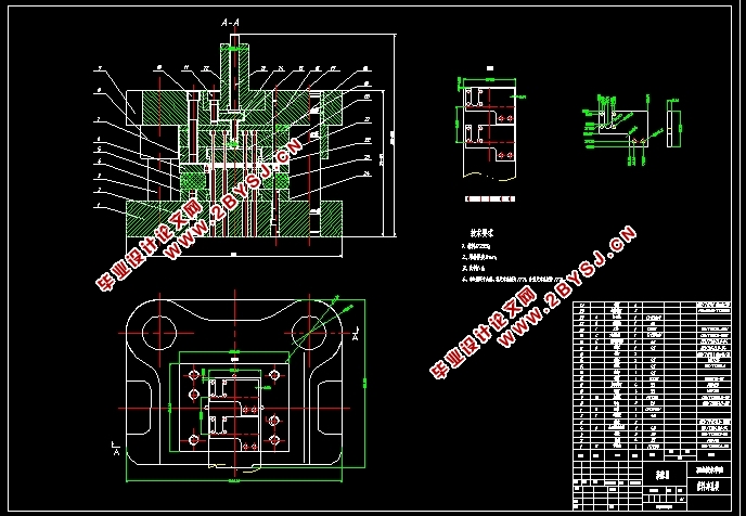
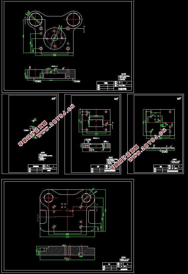
本文介绍了一个后轨道夹持机构成形过程,并且简要分析了坯料形状、尺寸,排样、裁板方案,冲压工序性质、数目和顺序的确定。进行了工艺力、压力中心、模具工作部分尺寸及公差的计算,并设计出模具。还具体分析了模具的主要零部件(如凸凹模、卸料装置、垫板、凸模固定板等)的设计与制造,冲压设备的选用,凸凹模间隙调整和编制一个重要零件的加工工艺过程。列出了模具所需零件的详细清单,并给出了合理的装配图。通过充分利用现代模具制造技术对传统机械零件进行结构改进、优化设计、优化工艺方法能大幅度提高生产效率,这种方法对类似产品具有一定的借鉴作用。
关键词: 冷冲压、压力中心、模具
Abstract
In this paper, the forming process of a rear track clamping mechanism is introduced, and the blank shape, size, layout and cutting plan, the determination of the nature, number and sequence of stamping process are briefly analyzed. The process force, pressure center, dimension and tolerance of the working part of the die were calculated, and the die was designed. The design and manufacture of the main parts of the die (such as punch and concave die, unloading device, cushion plate, punch fixing plate, etc.), the selection of stamping equipment, the adjustment of the gap between punch and concave die and the processing process of compiling an important part are also analyzed in detail. The detailed list of the parts needed by the die is listed, and the reasonable assembly drawing is given. By making full use of modern die manufacturing technology to improve the structure, optimize the design and optimize the process of traditional mechanical parts, the production efficiency can be greatly improved. This method has a certain reference for similar products.
Key words: cold stamping, pressure center, die


目 录
摘 要 3
第一章 零件的设计 5
1.1 零件图 5
1.2零件的工艺分析 5
1.3确定冲压工艺方案 5
1.4材料的选择 6
1.5操作与定位方式 6
1.6卸料与出件方式 6
第二章 冲压模具设计计算 8
2.1毛坯的展开计算 8
2.2排样图 8
2.3材料利用率 9
2.4冲裁力的计算 9
2.4.1落料力 9
2.5mm冲孔力 9
2.4.3卸料力 10
2.4.4推料力 10
2.4.5顶件力 10
2.4.7冲裁力的总和 10
2.5压力中心的计算 11
第三章 冲裁模间隙的确定 12
3.1间隙对冲裁件尺寸精度的影响 12
3.2间隙对模具寿命的影响 12
3.3间隙对冲裁工艺的影响 12
3.4间隙值的分析 12
第四章 工作部分尺寸计算 13
4.1刃口尺寸的计算 13
5mm冲孔凸、凹模的计算 14
第五章 工作零件结构设计 17
5.1凹模的设计 17
5.2外形凸模的设计 18
5.3内孔凸模的设计 18
第六章 辅助零件的设计 19
6.1选择模架 19
6.2模柄 19
6.3模具的闭合高度 20
第七章 装配图 21
总 结 22
致 谢 23
参考文献 24
