
高温高压下检测浮体的装置的结构设计(含CAD图)
无需注册登录,支付后按照提示操作即可获取该资料.
高温高压下检测浮体的装置的结构设计(含CAD图)(任务书,论文说明书16000字,外文翻译,CAD图纸4张)
摘 要
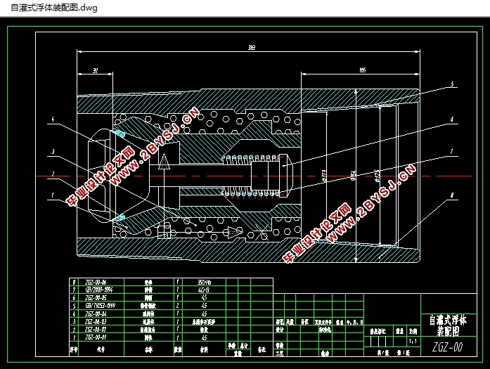
油田固井浮体在固井过程中起着控制水泥注入速度,避免水泥倒灌等作用。如果浮体失效,会降低固井质量,甚至引发事故。因此对浮体的耐高温、耐高压性能进行检验有利于提高我国固井的质量。本论文参照美国API(美国石油学会)的标准,建立一套对浮体进行高温高压性能检验的装置,使其能模拟浮体井下高温、高压和长时间连续工作的环境,该系统包括高温高压工作舱、加热系统和排油冷却系统等部分。
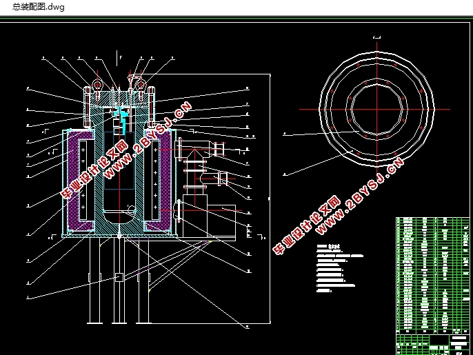
本文首先进行了高温高压工作舱的设计。工作舱中的高压釜是在高温高压环境下工作,其强度校核至关重要。本文在设计时采用了有限元分析方法对釜体进行了热-结构应力耦合分析,验算其最大应力是否满足设计要求。此外对工作舱上盖等其它组件进行了结构设计。
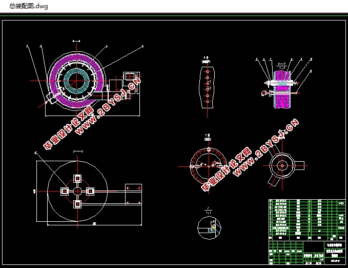
本文还对排油冷却系统和注油系统进行了设计。在确定了换热器类型的基础上,通过换热计算对传热面积进行校核,从而确定换热器尺寸,并对注油回路进行设计。
最后在完成加热系统设计之后进行了试验。加热系统设计包括加热类型的确定,炉膛尺寸和安装功率的计算。并对加热加压流程进行了设计,确定各测量温度。利用所研制的浮体高温高压性能检验装置进行了试验,根据试验提出了加热加压规程。
该项目的完成,不仅能检验我国浮体产品的质量,为企业增效益,提高浮体产品的售价,扩大国内市场,还可使浮体产品直接进入国际市场,有利于产品出口创汇以及推动我国石油化学工业的发展,提高我国在国际社会的地位。
关键词 浮体;高压釜;ANSYS;高温高压性能
Abstract
The oil-well cementing float equipment is used in controlling the speed to infuse the cement to the well and avoiding the cement to flow backward in the process of oilfield well-cementing. If the cementing float equipment is failure the quality of oil-well cementing will be reduced and it can even causing accident. It is important to detecting the capacity of high-temperature and high-pressure (HTHP) for the cementing float equipment so as to improve the quality of oil-well cementing in our country. A kind of testing equipment that to detect performance of the HTHP was established referring to the American API standard in this paper. It can simulate the environment of where HTHP condition and long time continuous work. The HTHP workspace furnace system and cooling system etc. were included in this system.
First, the HTHP workspace was designed in this paper. The HP vessel in workspace works in the environment of high-temperature and high-pressure and it is important to calculate its intension. In order to design reliable, the couple analysis of heat-stress was done to the cementing float equipment body using the finite element method so as to check whether the maximum stress to meet the design requirements. Additionally, the structure of the top cover of workspace and its components were designed in this paper too.
Secondly, the cooling system of discharging and oiling system were designed on the basis of determining the type of heat transfer. It was checked to the heat-transfer areas through calculated the dimensions were determined by it and the noting oil circuit system was designed.
At last, the experiment was done after the furnace system has been designed. The furnace system design includes determining the type of heating furnace and calculating the dimensions of chamber of the furnace and the installed power. The heating and pressing process was set up to measure the temperature. The test was done by using the HTHP equipment and the regulations of this system were given according to the test.
It is not only to test the quality of the float products increase efficiency for business raise the price of float products expand the domestic market, but also to make the products enter into the international market directly. It can conducive to make products export as well as to push the oil industry development and improve the position of our country in international society.
Keywords cementing float equipment;HPvessel;ANSYS;HTHP performance
工作舱设计参数确定
(1)工作舱工作基本要求
① 舱内有效工作内径为400mm,因工件最大外径为360mm,工作舱有效工作长度为1000mm;
② 舱内的工作压力为35MPa,工作温度为230℃;
③ 工作舱工作的环境温度为0~40℃;
④ 被测试件联结结构简单、拆装方便;
⑤ 在正常的工作条件下,釜体不发生塑性变形,密封可靠不泄露,安全使用总时间即工作舱寿命要大于(等于)2000小时
(2)设计压力
容器的设计必须考虑最高工作压力和最高工作温度可能同时出现的最苛刻条件的组合。设计压力取略高于或等于最高工作压力。

目 录
摘 要 I
Abstract II
第1章 绪 论 1
1.1 课题来源及研究目的和意义 1
1.2 国内外研究状况 2
1.2.1 国内高压釜研究状况 2
1.2.2 国外高压釜研究状况 3
1.3 有限元在高压釜设计中的应用 4
1.4 本文的主要研究内容 5
第2章 高温高压工作舱设计 7
2.1 浮体简介及浮体高温高压性能检验装置构成 7
2.1.1 浮体简介 7
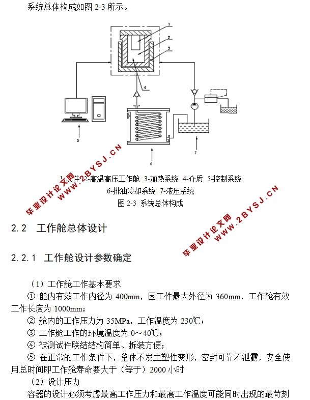
2.1.2 浮体高温高压性能检验装置构成 9
2.2 工作舱总体设计 10
2.2.1 工作舱设计参数确定 10
2.2.2 工作舱结构总体设计 11
2.3 釜体结构设计及有限元分析 13
2.3.1 釜体结构设计 13
2.3.2 釜体强度有限元分析 17
2.4 工作舱上盖组件设计 24
2.5 联接预紧力矩计算 26
2.6 本章小结 30
第3章 排油冷却系统及注油系统设计 31
3.1 换热器分类 31
3.2 换热器设计 31
3.2.1 换热计算 31
3.3 结构优化 36
3.4 注油系统设计 37
3.4.1 注油系统设计 37
3.4.2 液压站及管路设计要求 37
3.5 本章小结 38
第4章 加热系统设计及试验 39
4.1 加热方式及加热炉结构 39
4.1.1 加热类型及炉型分类 39
4.1.2 加热炉设计要求 39
4.1.3 炉膛尺寸计算 40
4.2 加热加压流程设计 41
4.2.1 主系统结构及传感器作用 41
4.2.2 系统加热加压流程设计 41
4.3 本章小结 43
结 论 44
致 谢 45
参考文献 46
附录1 译文 47
附录2 英文参考资料 50