
铣削组合机床及其主轴组件设计(含CAD零件图装配图)
无需注册登录,支付后按照提示操作即可获取该资料.
铣削组合机床及其主轴组件设计(含CAD零件图装配图)(任务书,论文说明书17000字,文献综述,CAD图纸4张)
摘 要
组合机床,它是大量通用组件和聚焦几个特殊元件,这台机器的高效加工。它的特点是: 结构紧凑,可靠的质量、 设计和制造周期短,投资少,良好的经济效果,效率高。
这个设计的主题是铣组合机床和主轴组件。首先要处理的部分,机床的整体设计,确定的机器和主轴设计的总体布局。机床主轴组件、 主轴的线索以满足需求的刚性和精度,其他人 (如轴承和轴向调节机制,锁定机制的设计,等等)各部分的设计。重要性和现代机械制造行业大有裨益,并展示了在该国的工业现代化战略的基础性作用,并已成为传统机械制造业的产业升级与自动化,柔软,综合生产和标记的重要手段。广泛应用于数控技术,数控铣床。机械工业结构、 产品类型和类,以及生产方式带来了革命性的变化。数控铣床是最重要的现代工艺厂房和设备。它是信息技术 (IT) 的开发和制造技术 (MT) 结合发展的结果。现代的 UG、 制造技术基于数字控制技术。知识是现代数控技术的数控技术学生的重要组成部分。也逐渐从数控CNC数控设备开发。其特点的高速度、效率高、精度高、可靠性高和模块化的,聪明,温柔和集成快速和方便的使它生产制造中越来越重要的作用。这篇文章的内容描述特征的数控加工、 机械加工工艺分析及数控编程的步骤。一些例子通过详细分析数控加工方法的过程。
关键词: 组合机床;纺锤体组装;刚度;轴;轴承;轴向调整机制
Abstract
Modular machine, by a large number of common components and in concentrated and efficient machine processing a small amount of special components. Features: Compact, reliable quality, shorten the design and manufacturing cycle, reduce investment and economic effects, as well as higher productivity.
His design portfolio theme milling spindle member.In the processing of first response, the overall design of paper machine, determine the overall layout of the machine. Then, the design of the pindle components. In the form of the design, the axis of spindle component, in order to meet the requirement of stiffness and accuracy, and perform Other (such as bearings, axial adjustment, locks, etc.) all parts of the design. the important position in the modern machinery Manufacturing and great benefits, and shows the fundamental role of the modern industrial state strategy in, has become the traditional mechanical manufacturing industry upgrading and automation,downy, integrated important means of production and marking. The wide application of numerical control technology, CNC milling machine. Machinery industry industrial structure, product types and classes, and mode of production has brought the revolutionary change. CNC milling machine is the most important modern processing workshop and equipment. IT is the development of information technology (IT) and the result of the development of manufacturing technology (MT) combined with. modernUG, manufacturing techniques, are based on numerical control technology. Knowledge of modern numerical control technology is an essential part of modern numerical control technology professional students. Also gradually from NC to CNC numerical control device development. Its characteristics of high speed, high efficiency, high precision, high reliability and its modular, intelligent, gentle and integration of quick and convenient to make it become more and more important role in the production and manufacturing. The characteristics of the content of this article introduced the numerical control processing, processing technology analysis and the general steps of nc programming. And through some examples the detailed introduces the analysis method of the nc machining process.
Keywords: module mechanism; main components; stiffness; shaft; bearing and axial adjustment
1.1 机床总体方案设计的依据
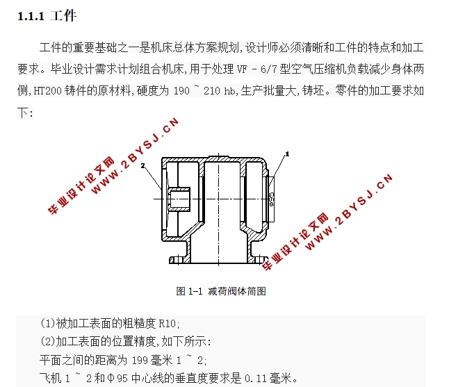
1.1.1 工件
工件的重要基础之一是机床总体方案规划,设计师必须清晰和工件的特点和加工要求。毕业设计需求计划组合机床,用于处理VF - 6/7型空气压缩机负载减少身体两侧,HT200铸件的原材料,硬度为190 ~ 210 hb,生产批量大,铸坯。
(1)被加工表面的粗糙度R10;
(2)加工表面的位置精度,如下所示:
平面之间的距离为199毫米1 ~ 2;
飞机1 ~ 2和φ95中心线的垂直度要求是0.11毫米。
1.1.2 刀具
YG6硬质合金端铣刀,铣刀齿材料,铣刀直径从75年~ 110年,刀齿Z = 4。
1.2 工艺分析
1.2.1 工艺方法的确定
过程方法的布局和功能车床很大,变化的过程的影响常常会导致车床的运动,传播、分布、结构、功能和经济的一系列剪切的影响。
飞机的处理方法有很多,如说把,铣削、刨平。VF - 6/7型空气压缩机负载减少,使用车床车削加工时,由于负载减少体型,外壳部分,不应夹在车床主轴加工、夹紧稳定性也不高,规划过程中,使用刨机需要两个动作,机床和刀具结构精致,工件的夹紧速度和固体,但生产率低,工件要求的加工精度也短;端铣刀在铣削,不仅提高了效率,能满足所需的加工精度,和夹紧迅疾,方便。
与普通车床相比,结合车床高生产率,加工精度稳定,开发周期短,易于设计、制造和使用维护,成本低、自动化程度高、劳动强度低、灵活等,因此,当生产很大,结合车床加工更合理。

目 录
摘 要 0
ABSTRACT 0
前 言 1
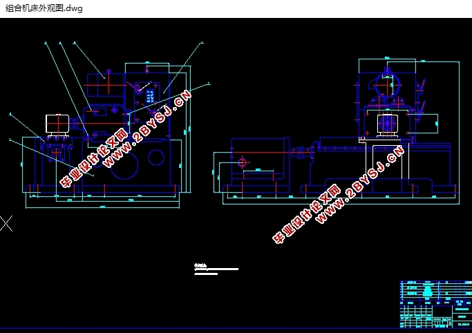
第一章 机床总体设计 1
1.1 机床总体方案设计的依据 1
1.1.1 工件 1
1.1.2 刀具 1
1.2 工艺分析 2
1.2.1 工艺方法的确定 2
1.2.2 机床总体布局 2
1.2.3 机床运动的确定 3
1.3 机床主要技术参数的确定 3
1.3.1 确定工件余量 4
1.3.2 选择切削用量 4
1.3.3 运动参数 4
1.3.4 动力参数—主运动驱动电动机功率的确定 6
1.4 进给驱动电动机功率的确定 7
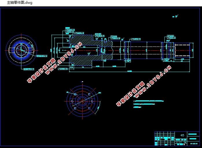
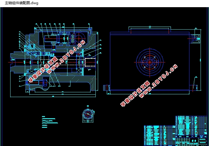
第二章 主轴组件设计 8
2.1 主轴的基本要求 8
2.1.1 旋转精度 8
2.1.2 刚度 8
2.1.3 抗振性 9
2.1.4 温升和热变形 11
2.1.5 耐磨性 11
2.1.6 其他 11
2.2 主轴组件的布局 12
2.2.1 适应刚度和承载能力的要求 12
2.2.2 适应转速要求 13
2.2.3 适应精度的要求 13
2.2.4 适应结构的要求 13
2.2.5 适应经济性要求 13
2.3 主轴结构的初步拟定 14
2.4 主轴的材料与热处理 15
2.5 主轴的技术要求 15
2.5.1 轴颈 16
2.5.2 内锥孔 16
2.6 主轴组件的计算 16
2.6.1 主轴直径的选择 16
2.6.2 主轴前后支承轴承的选择 17
2.6.3 主轴内孔直径 19
2.6.4 主轴前端悬伸量 19
2.6.5 主轴支承跨距 20
2.7 主轴结构图 21
2.8 主轴组件的验算 21
2.8.1 主轴端部挠度 21
2.8.2 支承的简化 21
2.8.3 主轴的挠度 22
2.8.4 主轴倾角 23
2.9 主轴组件的润滑和密封 24
2.9.1 主轴轴承的润滑 24
2.9.2 主轴组件的密封 24
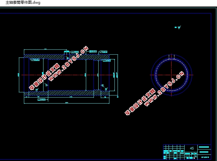
2.10 主轴组件中相关部件 26
2.10.1 轴肩挡圈 26
2.10.2 挡圈 26
2.10.3 圆螺母 26
2.10.4 套筒 27
2.10.5 前、后支承的轴承盖 28
2.10.6 主轴用套筒及其锁紧部分 29
2.10.7 主轴尾部的内花键 30
2.11 主轴组件轴向调节机构 31
2.11.1 丝杠螺纹 32
2.11.2 丝杠轴承的选择 32
2.11.3 丝杠螺母 33
2.11.4 丝杠中段螺纹 33
2.11.5 丝杠上的内隔套 33
2.11.6 丝杠上调节用锥齿轮 33
2.12 箱体设计 35
第三章 结论 36
参考文献 37
致 谢 38