
DP31-250机械压力机主机及传动系统设计(含CAD零件图装配图)
无需注册登录,支付后按照提示操作即可获取该资料.
DP31-250机械压力机主机及传动系统设计(含CAD零件图装配图)(课题申报表,任务书,开题报告,中期检查表,外文翻译,论文说明书15800字,CAD图纸6张,答辩PPT)
DESIGN OF THE MAIN ENGINE AND TRANSMISSION SYSTEM OF DP31-250 MECHANICAL PRESS
摘要
论文分析了压力机的发展历史背景,参阅了各类压力机的文章文献,基本确立了本次毕业设计的设计思路,本次设计的题目是DP31-250机械压力机主机及传动系统设计。本次设计的主要工作结构是曲柄滑块。其主要设计内容有压力机组成、分类及工作原理的掌握。对滑块进行运动分析;设计和计算偏心齿轮芯轴;对电动机进行选择和确定;完成飞轮的设计;完成传动系统中轴和齿轮的设计与计算等,并对压力机做了一些受力分析和强度校核的计算,使组件的参数能够符合设计的要求,验证出各部位的结构是合理可行的。
最后,通过cad和creo这些绘图软件完成了对压力机的三维实体造型、装配图及主要零部件图的设计与绘制,灵活运用各种知识串联设计出了一个符合设计要求的压力机及其说明书,并分析得出此次压力机的设计是可行的。
关键词 机械压力机;曲柄滑块;飞轮;传动系统
Abstract
In this paper, the historical background of press machine is analyzed, and the article literature of various press machines has been read, and the design idea of this design is basically established. The design of this design is the design of the main engine and transmission system of the DP31-250 mechanical press. The main structure of this design is crank slider. Its main design contents include the composition, classification and working principle of the press machine. The movement analysis of the slider, the design and calculation of the eccentric gear core shaft, the selection and determination of the motor, the design of the flywheel, the completion of the design and calculation of the shaft and gear in the transmission system, and the calculation of the force analysis and strength checking of the press, so that the parameters of the components can meet the requirements of the design. It is proved that the structure of each part is reasonable and feasible.
Finally, the design and drawing of 3D solid modeling, assembly drawing and main parts drawing of press are completed by CAD and Creo, and a press and instructions which meet the requirements of the design are designed flexibly with various knowledge, and the design of the press machine is feasible.
Keywords mechanical press; crank slider; flywheel; transmission system
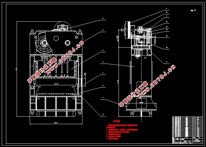
机械压力机工作原理及主要技术参数
曲柄压力机的结构图纸在1-1里面,通过电动机1进行工作,皮带轮2就给带着进行工作了,传动轴17带着飞轮3进行转动,偏心轮16的转动因为大齿轮5进行带动,之后因为连杆8的工作,这样滑块10就在立柱15里面的导轨9里面来回的进行动作。在滑块上将上模11固定上去,在机身工作台14的上面将下模12固定在上面。滑块动作时候的正确性主要是通过导轨来确保的,进行工作的时候,上面的模具还有下面的模具,是不会有水平方向上的错位的。电动机转动的时候,气压式刹车19就让曲柄滑块装置工作起来,或者是停下来了,让曲柄滑块装在在一个地方停下来。

目 录
摘要 I
Abstract II
1 绪论 1
1.1 机械压力机发展概况 1
1.2 机械压力机工作原理及主要技术参数 2
1.3 机械压力机分类 3
1.4 机械压力机研究现状 4
1.5 锻压设备的发展趋势 7
2 曲柄压力机工作机构的运动和受力分析 9
2.1 滑块的运动规律 9
2.1.1滑块的行程与曲柄转角的关系 9
2.1.2滑块的速度和曲柄转角的关系 10
2.1.3滑块的加速度和曲柄转角的关系 11
2.2 曲柄滑块机构的受力分析 12
3 偏心齿轮芯轴设计 13
3.1 结构概述 13
3.2 芯轴的强度计算 13
3.2.1芯轴直径经验公式 13
3.2.2单边传动芯轴强度计算 14
4 电动机选择 17
4.1 功能组成 17
4.2 电动机功率 18
5 飞轮转动惯量计算及尺寸确定 19
6 传动系统的布置与设计 21
6.1 传动系统的布置 21
6.2 传动级数和各级速比分配 22
7 传动零件的设计计算 24
7.1 齿轮的设计计算 24
7.2传动轴的设计计算 25
结论 30
致谢 31
参考文献 32