电涡流缓速器汽车辅助制动系统设计(含CAD零件图装配图)
无需注册登录,支付后按照提示操作即可获取该资料.
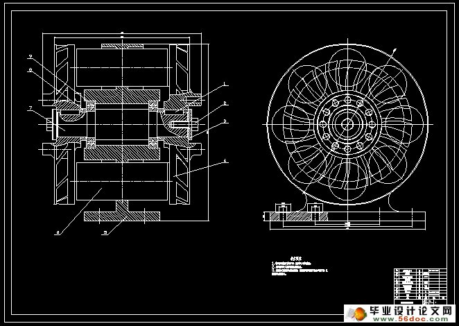
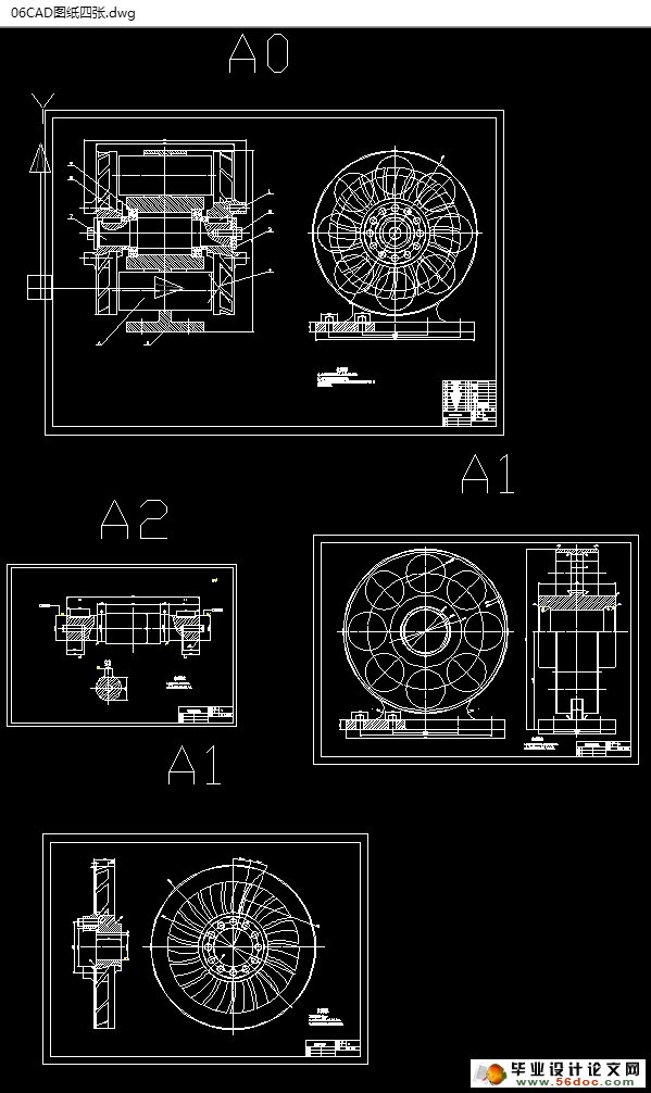
电涡流缓速器汽车辅助制动系统设计(含CAD零件图装配图)(任务书,开题报告,外文翻译,论文说明书14600字,CAD图纸4张)
摘 要
在汽车控制系统中,制动部分是非常重要的组成部分。汽车行驶过程中为了保持适当的车辆间隔和驾乘舒适度,精确控制刹车力矩显得尤为重要。对于紧急刹车情况,除了精确控制刹车力矩外,还要避免车轮抱死的情况发生。电涡流缓速器正是这样一种工具。
本文对电涡流缓速器的结构、工作原理、安装方式、使用性能等方面进行了阐述。从分析转子盘的涡流耗损入手,推导出了电涡流缓速器制动功率和制动力矩的计算公式,反映了电涡流缓速器各设计参数之间的关系,首先根据汽车的最高车速和后轴最大附着力来确定其所能达到的最大制动功率;其次选取和确定其应具有的气隙;然后再以此为基础完成对转子盘的各结构参数的设计计算。再次,分析了气隙、转子盘大小等因素对制动力矩的影响,找到结构设计的改进方向。最后,根据机械设计的知识设计电涡流缓速器的零件图。
关键词:电涡流缓速器,辅助刹车,结构设计
ABSTRACT
The braking part is very important in the control system of automobile.In order to keep the proper distance between the cars and the driving comfortable,the precisely control of braking torque is the most important.At the emergency,besides the accurately control of torque the instance of brake completely is need to be avoid.The eddy current retarder is such a tool.
The article introduces it’s the working primary, installing way and usability. From the analysis of the rotor disc’s loss,Deduced the calculation formula of the eddy current retarder braking power and braking torque ,Reflects the relationship between the various design parameters of the eddy current retarder. Firstly the maximum brake power of ECR is concluded by the maximum velocity of automobile and the maximum adhesion of rear axle. Then the air gap, magnetic induction of ferromagnetic and the area of magnetic yoke are given. Then the parameters of rotating disc and exciting winding are concluded. Next, analysis brake moment affected by the parameter of field coils, air gap and rotor disc. At last, According to mechanical design knowledge design for eddy current retarder the detail drawings.
Keywords: The eddy current retarder, Auxiliary Braking;Structural design.


目 录
前 言 1
摘 要 I
ABSTRACT II
第1章 绪 论 1
1.1电涡流缓速器简介 1
1.1.1 电涡流缓速器工作原理 1
1.1.2 电涡流缓速的结构基本组成 2
1.1.3 电涡流缓速器的分类 5
1.2 电涡流缓速器产品的优越性 6
1.2.1 选用电涡流缓速器的理由 6
1.2.2 电涡流缓速器的优越性 6
1.3 电涡流缓速器的发展概况 7
1.3.1国外电涡流缓速器的发展 8
1.3.2 国内电涡流缓速器的发展 9
第 2 章 电涡流缓速器主要结构设计 10
2.1电涡流缓速器的选型 10
2.2电涡流缓速器的设计 11
2.2.1重型货车参数 11
2.2.2电涡流缓速器最大功率确定 12
2.2.3 气隙的确定 12
2.2.4 气隙的作用面积 13
2.2.5 转子盘的结构参数 13
2.2.6制动力矩的理论推导 17
2.2.7涡流分布的深度 20
2.2.8制动力矩 21
第3章 缓速器转子轴的设计 23
3.1确定材料。 23
3.2计算轴的基本直径的确定 23
3.3 轴的结构设计 23
3.4各轴段的尺寸(直径和长度)的确定 24
3.4 校核轴的强度 24
3.5 校核该轴轴承的寿命。 25
第4章 结论及展望 26
4.1 结论 26
4.2 展望 26
致 谢 28
参考文献 29
