
流量为210t/h U型管式冷凝器(含CAD零件装配图)
无需注册登录,支付后按照提示操作即可获取该资料.
流量为210t/h U型管式冷凝器(含CAD零件装配图)(任务书,外文翻译,设计说明书14300字,CAD图纸9张)
摘要
换热设备在工业生产中的主要作用是能够使热量从温度比较高的流体传递到温度比较低的流体,从而使流体的温度达到工艺过程中规定的指标,满足工艺过程的需要。换热器中的管壳式换热器是目前应用最为广泛的一种换热设备,已作为一种标准换热设备[1]。这一种换热器的特点是比较容易制造,生产成本相对较低,选用材料的范围比较广,换热表面的清洁相对比较方便,适应能力较强,处理问题的能力较大,在高温和高压的情况下也可以使用[1]。与其他的换热器作比较,它的主要特点是在单位体积内的传热面积较大而且传热效果比较好。除此之外,它的结构简单,操作的弹性也大,所以在高温、高压的情况下以及在大型装备的应用上更多的使用管壳式换热器[1]。
本次设计的题目是“流量为210t/h U形管式冷凝器”,U型管式换热器是管壳式换热器的其中一种,它的结构主要包括管板、壳体、管束等零部件,重量相对比较轻。它将换热管弯成U形,并将换热管的两端固定在了同一块管板上,故而密封面比较少,达到了更加节能的原则。换热器的材料选用恰当,主要结构的尺寸也进行了合理的选择,均能够满足换热器在强度、刚度、稳定性以及水压试验等校核方面的要求。本次U型管式换热器设计的壳程介质为水,管程介质为水。流量为210t/h,壳程的工作温度为95℃,管程的工作温度为20℃,壳程的设计温度为70℃,管程的设计温度为60℃。在其结构上安装有八块折流板,以增加流体的湍流速度。设计压力为管程1.9MPa,壳程0.75MPa。依据给定的条件,查阅GB150-2011《钢制压力容器》,GB151-1999《管壳式换热器》以及换热器手册等标准,通过试算法获得总传热系数,所得传热面积为193.4m².考虑到介质特性,采用φ25×2×6000的Q345R的无缝钢管,本设计采用412根换热管可以满足换热量。接管法兰我选取了板式平焊法兰,并选用鞍式支座支撑。在本次毕业设计过程中我已经完成了文献综述,设计说明书,一张总装配图和三张零件图的绘制。
换热器在工业、农业等许多的领域运用十分的广泛,当然在日常生活中和现实中的传热设备也随处可以见到,是不可能缺少的工艺设备和单元之一。随着研究的不断深入,工业应用也取得了显著的成效。并且在许多化工单元操作的场合也作为一种十分重要的附属设备进行使用,所以在化工生产中换热器也占有着非常非常重要的地位。
关键词: 换热器; 管壳式; U形管; 管板;
Abstract
Heat exchange equipment in industrial production, the main effect is to be able to make heat from high temperature fluid to the lower temperature of fluid, so that the temperature of the fluid can reach the indexes of the specified in the process, meet the needs of the process. In the heat exchanger tube and shell heat exchanger is the most widely used, a heat exchange equipment has as a standard heat exchange equipment. The characteristics of this kind of heat exchanger is relatively easy to manufacture, the production cost is relatively low, and the use of material range is wide, so the heat exchange surface cleaning is relatively simple, strong ability to adapt, ability to handle problems, in the case of high temperature and high pressure can also use. Compare to other heat exchanger, its main characteristic is in heat transfer area per unit volume is larger and the heat transfer effect is better. In addition, its structure is simple, the operation of the elasticity is big, so in the case of high temperature and high pressure, and the application of in large-scale equipment on the use of more tube and shell heat exchanger.
The topic of this design is the \"flow of 210 t/h\" of u-tube heat exchanger, the U tube heat exchanger is one of the tube and shell heat exchanger, and its structure mainly includes the tube plate, shell and tube bundle components, relatively light in weight. It will be bent into a u-shaped heat exchange tube, and the two end of heat exchange tube fixed on the same piece of tube plate, sealing surface is less so, to the principle of more energy efficient. Heat exchanger of the proper material selection, the size of the main structure is a reasonable choice, all can satisfy the heat exchanger in strength, stiffness, stability, and water pressure test requirements. The shell side of the U tube heat exchanger design medium for water, in the medium for oil passes. The shell side of the flow rate of 210 t/h, the working temperature of 95 ℃, monitor the working temperature is 20 ℃, the design of the shell side temperature is 70 ℃, the design of tube side temperature is60 ℃. In eight pieces of baffle are installed on the structure, to increase the turbulence velocity of the fluid. The shell side of the design pressure for the coil 1.9 MPa, 0.75 MPa. According to the given conditions, consult the GB150-2011 \"steel pressure vessel\" and GB151-1999 \"tube shell heat exchanger and heat exchanger manual such as standard, through the test algorithm to obtain the total heat transfer coefficient, the heat transfer area of 193.4 m squared. Considering the medium characteristic, adopt the phi 25 x 2 x 6000 Q345R of seamless steel tube, the design adopts 412 heat exchange tube can meet the change of heat. Nozzle flange I selected the plate flat welding flange, and selects the saddle support. I have already finished in the process of the graduation design review, design specifications, three part drawing and the drawing of a general assembly drawing.
Heat exchanger used in many fields such as industry, agriculture is very wide, heat transfer equipment in daily life and reality, of course, also can be seen everywhere, it is impossible to a lack of process equipment and one of the unit. With the deepening of the research, industrial application has made significant achievements. Occasions and in many chemical unit operations are also used as a kind of important auxiliary equipment, so the heat exchanger in chemical industry production also plays a very important position.
Keywords: Heat exchanger; Shell and Tube; U-shaped tube; Tube plate.


目 录
第一章、换热器的综述 1
引言 1
1.1 换热器 1
1.2 换热器的发展前景 2
1.3 换热器的工作原理 3
1.4 管壳式换热器类型 3
1.4.1 固定管板式换热器 3
1.4.2 浮头式换热器 4
1.4.3 U形管式换热器 5
1.4.4 填料函式换热器 7
1.5结语 ......... 8
参考文献 ...................... 9
第二章、设计说明书 10
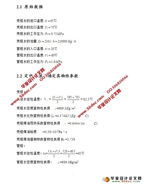
2.1 原始数据 10
2.2 定性温度及确定其物性参数 10
2.3传热量与水流量计算 11
2.4有效平均温差计算 11
2.5管程换热系数计算 12
2.6结构的初步设计 12
2.7壳程换热系数计算 13
2.8 传热系数计算 14
2.9 管壁温度计算 14
2.10壳程压力降计算 14
2.11 管程压力降计算 15
第三章、U型管换热器结构设计计算 17
3.1换热管材料及规格的选择和根数的确定 17
3.2管子的排列方式 17
3.3筒体内径的确定 17
3.4筒体壁厚的确定 18
3.5 筒体水压试验 18
3.6 壳程标准椭圆形封头厚度的计算 19
3.7 管程标准椭圆形封头厚度的计算 20
3.8容器法兰的选择 21
3.8.1设备法兰的选择 21
3.8.2接管法兰的选择 23
3.9管板的设计 23
3.10管箱短节壁厚的计算 25
3.11 拉杆和定距管的确定 26
3.12折流板的选择 26
3.13防冲板尺寸确定 27
3.14 接管及开孔补强 28
3.15 支座的选择及应力校核 32
3.15.1 支座的选择 32
3.15.2 鞍座的应力校核 33
致谢 37
附 录
4.2英文翻译