
移动手柄的工艺工装设计
无需注册登录,支付后按照提示操作即可获取该资料.
移动手柄的工艺工装设计(设计说明书7600字,cad图纸15张)
摘要 现代机械加工行业发生着深刻的结构性变化,工艺工装的设计与改良已成为企业生存和发展的必要条件。工艺工装的设计与改良直接影响着连杆盖的质量与性能。连杆盖行业作为一个传统而富有活力的行业,近十几年取得了突飞猛进的发展。在新经济时代,连杆盖行业呈现了新的发展趋势,由此对其连杆盖质量、性能产生了新的变化。
本文首先介绍了连杆盖的作用和工艺分析,其次确定毛坯尺寸,然后进行了工艺规程设计,最后对第30道工序和第50道工序进行了夹具设计
关键词:工艺分析 工艺规程设计 夹具设计
The design of the connecting rod cap ‘s technical frock
Abstract A profound structural movement is taking place in the modern machine process industry, so the design and improvement of the technical frock have become the necessary condition for the corporation to live and develop. the design and improvement of the technical frock directly affect the quality and performance of the connecting rod cap. The connecting rod cap industry which is traditional and vivid has much developed in recent ten years. In new economy times , The cap industry presents a new developing trend. So there is a new requirement to its quality and performance.
This paper introduces the effect and technical analyse of the Connecting rod cap at first , then makes sure the rough’s size, planning the technical rules , at last designs the modular for the 30th and 50th working procedure .
Key words technical analyse the technical rules plan modular design
.零件的结构工艺分析
所谓零件的结构工艺性是指设计的零件在满足使用要求的前提下,其制造。
的可行性和经济性
由附图零件图得知,其材料为HT200,该材料具有较高的强度,耐磨性,耐热性及减振性.适用于承受较大应力,要求耐磨的零件.
该零件的主要加工面为N面R面Q面D面及宽为35的两槽面和φ42H7,φ35H7, φ42,φ20H7的孔.
N面R面的粗糙度为Ra12.5um,Q面D面的粗糙度为Ra3.2um. φ42H7,φ35H7的孔的同轴度为0.03且两孔的粗糙度Ra为 3.2um, φ42的孔内壁粗糙度为12.5um, 2-φ20H7的孔内壁粗糙度Ra为 1.6um,宽度为35+0.34的槽两侧壁的粗糙度Ra为3.2um,在前部φ42H7的孔与2-φ20H7的孔圆心距为46.37mm加工这些时最好能在一次装夹下同时加工出来,同时也可以采用互为基准的原则进行互定位.
由参考文献(1)中的有关方面和孔加工,面槽铣的经济精度及机床所能达到的位置精度可知,上述技术要求是可以达到的,零件的结构工艺性也是可行的.
目 录
引言………………………………………………………………………………… 3
第一章 零件的分析…………………………………………………………… 3
1.1 零件的作用……………………………………………………………… 3
1.2 零件的工艺分析………………………………………………………… 3
第二章 确定毛坯,画毛坯图……………………………………………… 4
第三章 工艺规程设计……………………………………………………… 5
3.1 定位基准的选择………………………………………………………… 5
3.2 加工工艺路线…………………………………………………………… 6
3.3 选择加工设备及刀具,夹具,量具…………………………………………7
3.4 加工工序设计………………………………………………………………7
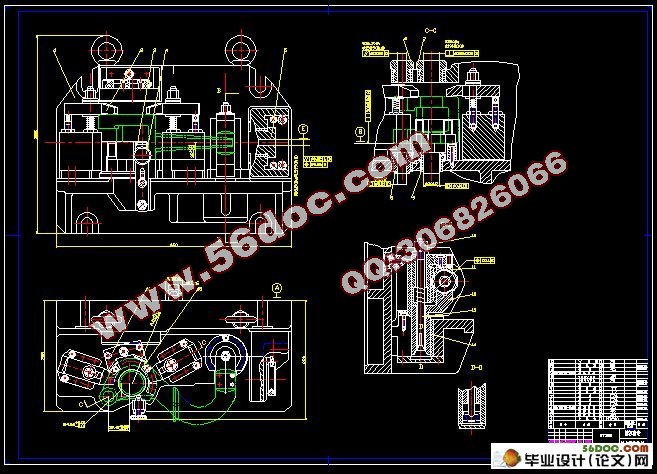
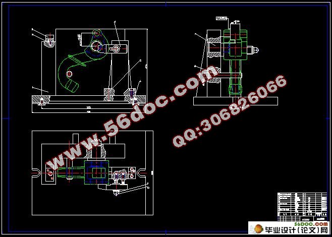
第四章 夹具设计 …………………………………………………………… 11
4.1 第30道工序的夹具设计………………………………………………11
4.1.1 确定设计方案…………………………………………………………11
4.1.2 计算夹紧力并确定螺杆的直径………………………………………12
4.1.3 定位精度分析………………………………………………………… 12
4.2 第50道工序的夹具设计……………………………………………… 13
4.2.1 确定设计方案………………………………………………………… 13
4.2.2 定位精度分析………………………………………………………… 13
结论………………………………………………………………………………… 14
致谢………………………………………………………………………………… 15
参考文献…………………………………………………………………………… 16