
内燃机进气管玉柴200系列夹具设计(含工序卡)
无需注册登录,支付后按照提示操作即可获取该资料.
内燃机进气管玉柴200系列夹具设计(含工序卡)(任务书,开题报告,外文翻译,进度计划表,论文说明书20000字,cad图纸4张,工序卡)
摘要
本 设计主要包括两方面的内容,即进气管的加工工艺规程设计以及典型的加工工序的夹具设计。本文对一个常规工艺设计及的步骤做了详细阐述。在此基础上对零件加 工要求进行分析,最终确定毛坯的材料,选择定位基准,并留出适当的加工余量。综合上述分析可以制定出零件加工工艺路线中的具体参数进行计算,例如基本的切 削用量的计算,并根据计算结果选择机床,验算机床功率,此外,计算加工过程中的机动时间和辅助时间也是必不可少的。
机械加工工艺过程,是指用机械加工方法逐步改变毛坯形态(形状、尺寸和表面质量),使之成为合格零件所进行的全部过程。
机 械加工工艺过程包括结构工艺性分析、毛坯的选择、基准的选择、加工余量的确定、工艺路线的拟定、工序尺寸及公差的确定和加工设备的选择等。工艺路线是连接 产品设计和制造的纽带,它是一项经验性强、技巧性高、涉及多方面的知识和信息的工作,因此工艺路线设计极其复杂,其中,加工顺序的先后、热处理的安排和工 序的集中还是工序的集中与分散是工艺人员在拟定工艺路线时的原则性问题。
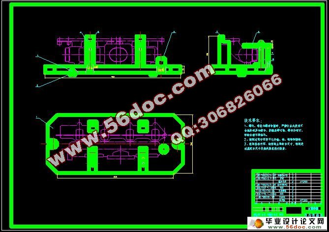
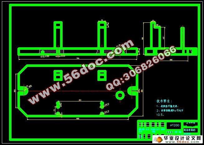
为了提高劳动生产率,保证加工质量和改善劳动条件,需要设计专用的夹具。 在夹具设计中,不仅要追求其其结构的合理性,更重要的是核算其加工精度的准确性。影响工件加工精度的因素很多,且种类复杂。本夹具的设计是完成定位设计、 夹紧设计等,以及如何将这些机构装配起来形成一个整体 装配过程。结构方案确定以后,绘制了主要的零件图装配图。
关键词:加工工艺;切削用量;工艺计算;夹具设计。
ABSTRACT
This design mainly includes two aspects of content, namely the intake pipe processing process planning and typical processing process of fixture design. In this paper a conventional process design and steps to do a detailed description. On the basis of the parts processing requirements analysis, with a final determination of blank materials, choose the locating datum, and set aside the proper machining allowance. A combination of the analysis can work out the parts processing process route in the specific parameters calculation, such as basic of cutting parameter calculation, and according to the calculated results choose machine tool, the checking machine power, in addition, the calculation process, mobile time and auxiliary time is also essential.
Mechanical processing, it is to point to by machining methods gradually change the blank form (shape, size and surface quality), make it become the qualified the process all parts.
Mechanical processing process including structure analysis technology, the choice of blank, the choice of machining allowance benchmark, the determination, process route of the recommended, and the determination of the procedure sizes tolerance and processing equipment choice, etc. Process line is the connection product design and the manufacture of the link, it is a critical skill, high, strong a wide range of knowledge and information work, so process route design is extremely complex, among them, the processing order has the arrangement and working procedure, heat treatment process of concentration or centralized and decentralized is in planning process engineering process route of principle problem.
In order to improve labor productivity, guarantee the processing quality and improve working conditions, and need to design a special fixture. The fixture design, we not only need to pursue the rationality of the structure, more important is the accuracy of accounting the machining accuracy. The influence the machining accuracy of many factors, and species complex. This fixture design is complete orientation design, clamping design, and how these institutions together to form a whole assembly process. Structure plan later, rendering the main parts drawing assembly drawing.
Key words: process, the cutting dosages, process calculation, fixture design.
零件的功用
进 气管的作用就是按照柴油机的工作次序,分别供给各缸充足的新鲜空气。进气管一般用铸铁或铝合金铸造。进气管和排气管分别安装在汽缸盖的两侧,如果在一侧装 配,会使排气管的高温传给进气管,造成进入汽缸内的空气密度减小,影响进气量。同时,为了减小空气的流通阻力,进气管内壁一般要做得比较平整和光滑。
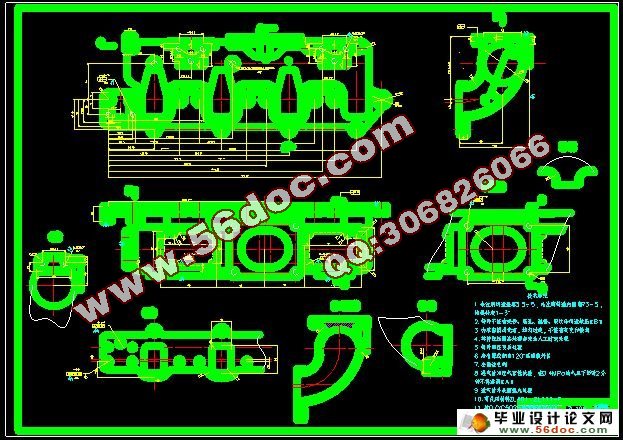
从零件图上可以看出,该进气管的结构比较复杂,需要加工表面多,其主要加工表面可以分为四个部分:
(1)其主要加工表面为后表面、14×Φ11的孔和2×Φ8的孔所在表面。
这一组加工面包括:后表面,14×Φ11孔,2×Φ8孔;
(2)前表面。
这一组加工面包括:前表面,6×M10-7H,2×M10×1-7H的螺纹孔;
(3)上表面。
这一组加工面包括:上表面,6×Φ2.96±0.05的孔,4×M10-7H的螺纹孔,
6×Φ2.96±0.05的孔;
(4)左端面。
这一组加工面包括:左端面,2×M10-7H的螺纹孔。
以上各组加工面的技术要求如下:
(1)表面粗糙度要求为Ra6.3,有平面度要求,Φ11孔的位移度要求为0.4,M8-7H的螺纹孔位移度要求0.4;
(2)表面粗糙度要求为Ra6.3,螺纹孔的精度要求为7H;
(3)上表面表面粗糙度要求为Ra12.5,孔尺寸精度及形位公差要求较高,螺纹孔精度要求为7H,孔Φ2.96的尺寸精度要求为±0.05;
(4)表面粗糙度要求为Ra12.5,螺纹孔的精度要求为7H,孔内表面粗糙度要求为Ra16.3。
由以上可以分析,对于这四组加工表面来讲,可以先选择其中一组加工表面进行加工,然后再以加工过的表面为基准,加工其他三组表面,并保证他们之间的相互位置精度。

目 录
摘要 Ⅲ
ABSTRACT Ⅳ
目录 Ⅴ
1 绪论 1
1.1本课题的研究内容和意义 1
1.2国内外的发展概况 1
1.3本课题应达到的要求 2
2 零件的分析 3
2.1零件的功用 3
2.2 零件的工艺分析 3
3 零件的工艺规程设计 5
3.1 确定零件的生产类型 5
3.2 材料的选择 5
3.3 确定零件毛坯的制造形式 5
3.4 拟定零件的机械加工工艺路线 5
3.4.1定位基准的选择 5
3.4.2零件表面加工方法的选择 6
3.4.3零件各表面加工顺序的确定 6
3.4.4工序的组合 6
3.5 工序设计 6
3.6 工艺计算 7
3.6.1 铣后表面的工艺计算 8
3.6.2 钻后表面上孔的工艺计算 10
3.6.3 铣前表面的工艺计算 12
3.6.4 钻前表面上孔的工艺计算 14
3.6.5 铣上表面的工艺计算 14
3.6.6 钻上表面上孔的工艺计算 15
3.6.7 铣凸台面的工艺计算 17
3.6.8 铣左端面的工艺计算 17
3.6.9 钻左端面上孔的工艺计算 18
4 夹具设计 19
4.1夹具设计概述 19
4.2 机床夹具的分类 19
4.3 机床夹具的基本组成 19
4.4 夹具设计 19
4.4.1 铣后表面夹具设计 23
4.4.2 铣前表面夹具设计 23
4.4.3 钻左端面孔夹具设计 24
4.5 夹具图装配图上的标注 24
4.6 定位误差的分析和计算 25
4.6.1定位误差的分析 26
4.6.2定位误差的计算 27
4.7夹紧力的分析与计算 29
5结论与展望 31
5.1结论 31
5.2不足之处及未来展望 31
致 谢 32
参考文献 33
附 录 34