
调距镜筒机械加工工艺规程及夹具设计(含CAD,SolidWorks三维图)
无需注册登录,支付后按照提示操作即可获取该资料.
调距镜筒机械加工工艺规程及夹具设计(含CAD,SolidWorks三维图)(论文说明书9500字,CAD图纸4张,SolidWorks三维图1张,工艺卡,工序卡)
摘要:在生产过程中,使生产对象(原材料,毛坯,零件或总成等)的质和量的状态发生直接变化的过程叫工艺过程,如毛坯制造,机械加工,热处理,装配等都称之为工艺过程。在制定工艺过程中,要确定各工序的安装工位和该工序需要的工步,加工该工序的机车及机床的进给量,切削深度,主轴转速和切削速度,该工序的夹具,刀具及量具,还有走刀次数和走刀长度,最后计算该工序的基本时间,辅助时间和工作地服务时间。
关键词:工艺过程;毛坯;进给量;走刀长度;
Abstract:Enable producing the target in process of production (raw materials, the blank , state of quality and quantity on part become always ) take place direct course of change ask craft course, if the blank is made, machining, heat treatment , assemble etc. and call it the craft course. In the course of making the craft , is it confirm every erector location and worker step that process need this of process to want, the locomotive of processing , this process , and the entering the giving amount of the lathe, cut depth , the rotational speed of the main shaft and speed of cutting, the jig of this process, the cutter and measuring tool, a one hundred sheets of number of times still leaves and a one hundred sheets of length leaves, calculate basic time of this process , auxiliary time and service time of place of working finally.
Key Word: The process;worker one;orient the scheme;
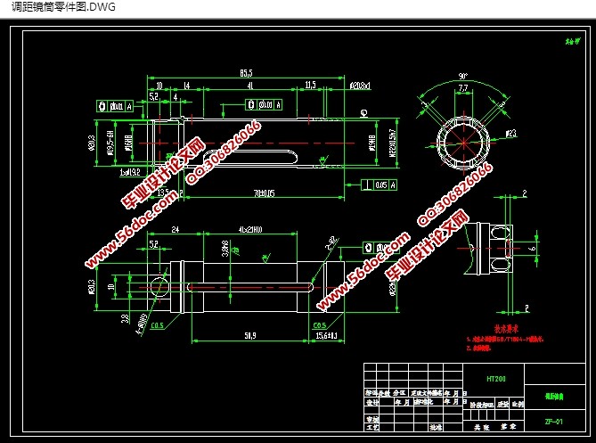
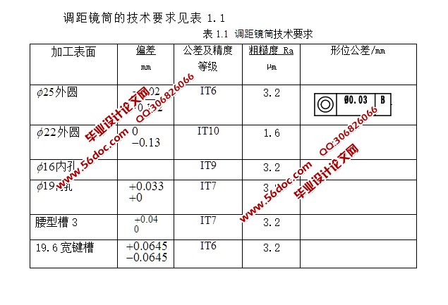
调距镜筒工艺分析
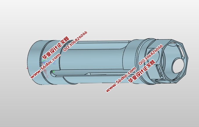
分析可知本零件材料为3Cr13钢。该零件具有较高的强度,耐磨性,耐热性,减震性,适应于承受较大的应力,要求耐磨的零件。调距镜筒具有几组外圆表面,他们之间有一定的位置要求。
由零件图可知,外圆 内孔的中心线是主要的设计基准和加工基准。该零件的主要加工面可分为两组:
1.以 等工序为主要加工面的加工表面
这一组加工表面包括: 的车削加工及端面及孔和倒角。
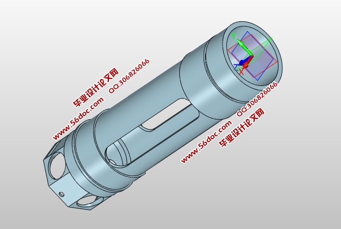
2.以左视图为主要加工表面的加工面
这一组加工表面包括, 腰槽的铣削加工,M1.6-6H的钻、攻削加工等。
由以上分析可知,对这两组加工表面而言,先加工第一组,再加工第二组。由参考文献中有关面和孔加工精度及机床所能达到的位置精度可知,上述技术要求是可以达到的,零件的结构工艺性也是可行的。另外考虑到零件的精度不高可以在普通机床上加工。
目录
摘要 Ⅰ
ABSTRACT Ⅱ
第一章 绪论 1
1.1 选题的意义 3
1.2 夹具的发展方向 3
1.3 本章小结 6
第二章 调距镜筒的加工工艺规程设计 8
2.1 调距镜筒的作用 9
2.1.2调距镜筒的技术要求 10
2.2 调距镜筒的工艺分析 11
2.3 确定毛坯,绘制毛坯简图 11
2.3.1选择毛坯 12
2.3.2确定毛坯的尺寸公差和机械加工余量 12
2.4 拟定调距镜筒工艺路线 13
2.4.1定位基准的选择 13
2.4.2精基准的选择 15
2.4.3粗基准的选择 16
2.5各面、孔加工方法的确定 17
2.6加工阶段的划分 18
2.7工序的集中于分散 19
2.8工序顺序的安排 20
2.8.1机械加工工序 21
2.8.2热处理工序 22
2.8.3辅助工序 22
第三章 机床设备及工艺装备的选用 23
3.1 机床设备的选用 23
3.2 工艺装备的选用 23
第四章 切削用量与时间定额的计算 23
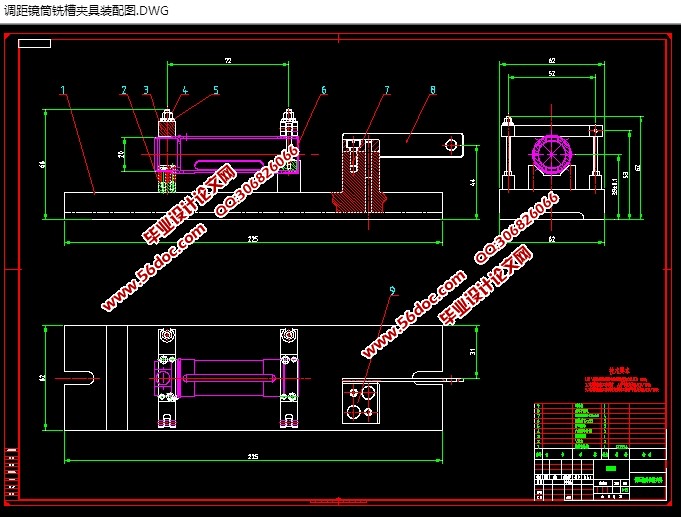
第五章 夹具设计 24
5.1 问题的提出 25
5.2 定位方案 26
5.3 夹紧机构 27
5.4 夹具与机床的联接元件 28
5.5 定位误差分析 29
5.6 切削力及夹紧力的计算 30
结论 31
参考文献 32
致谢 33