气动机械手设计(含CAD零件图和装配图,原理图,梯形图)
无需注册登录,支付后按照提示操作即可获取该资料.
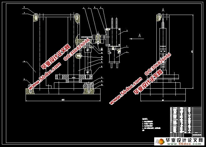
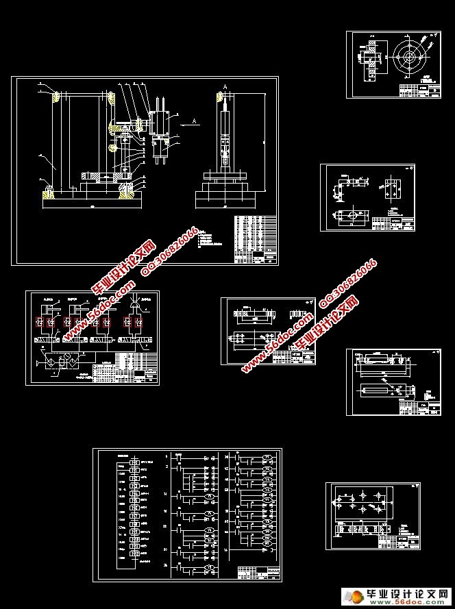
气动机械手设计(含CAD零件图和装配图,原理图,梯形图)(开题报告,论文说明书18000字,CAD图8张)
摘 要:气动机械手是能模仿人手和臂的某些动作功能,用以按固定程序抓取、搬运物件或操作工具的自动操作装置。它可代替人的繁重劳动以实现生产的机械化和自动化,能在有害环境下操作以保护人身安全,因而广泛应用于机械制造、冶金、电子、轻工和原子能等部门。
本文主要进行了气动机械手的总体结构设计、气动设计和PLC控制系统。机械手的机械结构由气缸、气爪和连接件组成,可按预定轨迹运动,实现对工件的抓取、搬运和卸载。气动部分的设计主要是选择合适的控制阀,设计合理的气动控制回路,通过控制和调节各个气缸压缩空气的压力、流量和方向来使气动执行机构获得必要的力、动作速度和改变运动方向,并按规定的程序工作。
关键词:气动机械手;气动回路;PLC控制系统
The design of pneumatic manipulator
Abstract: Pneumatic manipulator is a automated devices that can mimic the human hand and arm movements to do something,also can according to a fixed procedure to moving objects or control tools. It can replace the heavy labor in order to achieve the production mechanization and automation, and can work in dangerous working environments to protect the personal safety, Therefore widely used in machine building, metallurgy, electronics, light industry and atomic energy sectors.
This article is mainly of the pneumatic manipulator the overall design, pneumatic design and PLC control system. This mechanism of manipulator includes cylinders and claws and connectors parts, it can move according to the due track on the movement of grabbing, carrying and unloading. The pneumatic part of the design is primarily to choose the right valves and design a reasonable pneumatic control loop, by controlling and regulating pressure, flow and direction of the compressed air to make it get the necessary strength, speed and changed the direction of movement in the prescribed procedure work.
Key words: pneumatic manipulator;pneumatic loop;PLC control system
设计内容
要求设计其技术参数为:
(1) 抓重:10Kg (夹持式手部)
(2) 自由度数:4个自由度
(3) 标型式:圆柱座标
(4) 最大工作半径:1000mm
(5) 手臂最大中心高:600mm
根据所给的设计参数,设计气动机械手。
(1) 确定机械手总体传动方案,查阅相关资料
(2) 对主要零件进行设计计算,选定各标准件
(3) 绘制机械手总装图
(4) 绘制部分自制零件的工程图
(5) 编写设计说明书


目 录
摘要 1
关键词 1
1 前言 2
1.1 选课研究意义 2
1.2 国内外气动机械手发展简史概况 2
1.3 国内气动机械手未来发展方向 4
1.4 目前国内常见的机械手类型 4
1.4.1 按驱动方式分类 4
1.4.2 按用途分类 5
1.4.3 按操作机的位置机构类型和自由度数量分类 5
1.4.4 按其他方式分类 5
1.5 气动机械手的组成 5
2 总体方案拟定 7
2.1 原理分析 7
2.1.1 目的 7
2.1.2 设计内容 7
2.1.3 方案选择 8
2.1.4 方案的比较 9
2.2 总体结构方案 9
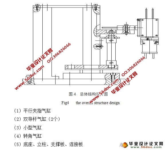
2.2.1 总体结构 9
2.2.2 机械手的运动规划 10
2.2.3 机械手主要部件以及运动 10
2.3 各执行机构主要参数的初步确定 11
2.3.1 设计技术参数 11
2.4 气动回路的设计和参数的计算 11
3 主要部件的选择和设计 12
3.1 机械手末端执行器的设计 12
3.1.1 平行夹指气缸的设计 12
3.1.2 末端执行器的运动和驱动方式 12
3.1.3 末端执行器的典型结构 13
3.1.4 末端执行器的具体设计 13
3.2 机械手臂设计要求 15
3.2.1 机械手臂设计要求 15
3.2.2 机械手臂具体设计方案前活塞杆上输出力和缸径的计算 16
3.2.3 机械手臂的具体设计方案 17
3.2.4 伸缩手臂的设计 18
3.2.5 升降手臂的设计 20
3.3 机械手臂腰部的设计计算 22
3.3.1 回转部分的设计 22
3.4 机械手中横梁的设计计算 24
3.4.1 载荷计算 24
3.4.2 强度计算 25
3.5 机械手底座的设计 26
4 气动机械手控制系统的设计 26
4.1 系统结构和功能介绍 27
4.2 PLC控制系统的设计 28
4.2.1 PLC I/O 表和I/O连接图 28
4.2.2 控制程序设计 29
5 结束语 30
参考文献 31
致谢 32
附录 33
附录 1:机械手气压控制的动作程序
附录2:装配图A0一张
附录3:零件图A3五张
附录4:原理图A2一张
附录5:控制梯形图A1一张
