
驱动圆盘犁尾轮装置结构设计
无需注册登录,支付后按照提示操作即可获取该资料.
驱动圆盘犁尾轮装置结构设计(任务书,开题报告,论文说明书8700字,CAD图纸8张)
摘要
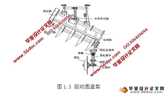
本文是对目前市场上的驱动圆盘犁尾轮装置进行改装设计,使尾轮能够横向位置可调、上下位置自动调节以及实现偏角和倾角的调节,以此使尾轮装置可以保证驱动圆盘犁可以在不同硬度土壤的环境下仍能平稳正常工作。本文对尾轮整个装置的结构进行研究设计,通过对连接架和摆杆的结构设计,实现横向位置可调以及二者与导杠和弹簧装配后可以实现尾轮上下自动调节;然后颠覆以往尾轮倾角和偏角不能调节的理念,提出对尾轮装置的改进方案。其一,把尾轮的摆杠从中间切断并各自焊接一个法兰盘,然后通过对法兰盘的结构设计来实现两段摆杠相对位置的变化,进而实现尾轮倾角的可调;其二,设计偏心轴体和尾轮轴体,利用两者的配合,使摆杠和尾轮轴体发生相对位置变化,以此来实现尾轮偏角的变化。尾轮倾角和偏角的可调节的实现可以使驱动圆盘犁满足不同土质的田地,大大的增加了驱动式圆盘犁的适用场合,并且保证驱动圆盘犁的工作质量。
关键词:尾轮;偏角;倾角;法兰盘
Abstract
This paper is on the current market driven disc plow tail wheel device for design modifications, the tail wheel to lateral position can be adjustable, upper and lower position automatic adjustment, and regulate the declination and inclination of the, in order to make the tail wheel device can ensure the driving disk plow can under the environment of soil with different hardness can still work smoothly. In this paper, the structure of tail wheel the whole device to study design, through the connecting frame and structure design of swinging rod, adjustable and two with a guide bar and a spring assembly can be achieved after the tail wheel is the automatic adjustment of the lateral position; then subvert previous tail wheel angle and angle can not adjust the concept, put forward the improvements on the tail wheel device. First, the tail wheel pendulum bar from the middle cut and their welding a flange plate, followed by the structure design of the flange to achieve two pendulum bar relative position changes, so as to realize the rear wheel angle adjustable; second, design of eccentric shaft body and tail wheel body, with use of the two, pendulum bar and the tail shaft body relative position changes, in order to realize the rear wheel angle changes. Tail wheel angle and angle adjustable implementation can make the driving disk plow meet different soil fields, greatly increases the driving disk plow the suitable situation, and ensure the driving disk plow work quality.
Key word:tailwheel Drift angle Inclination flange plate
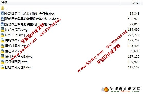
尾轮装置的设计要求
(1)左右位置二级可调;
(2)尾轮倾角可调;
(3)尾轮偏角可调;
(4)尾轮上下位置自动调节。
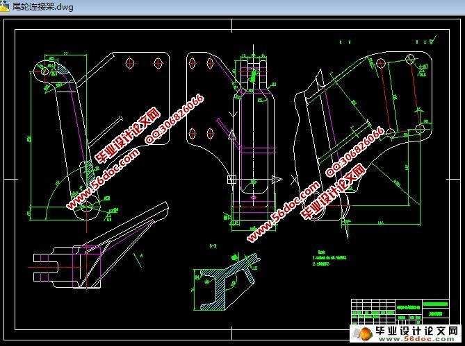
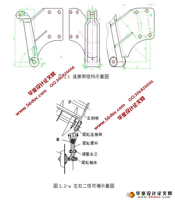
尾轮连接架结构设计
尾轮连接架是用于尾轮装置与驱动圆盘犁机组连接的部分。连接架的结构是由连接臂和连接板焊接在一起的。连接臂设计成一根斜杠,与x轴负方向倾斜75°,连接臂的上端是沿杠逆时针弯曲90°的圆形端头,并设有直径为14mm的导杠销孔,用于与导杠连接;下端是直径为50mm的圆形端头,并设有直径为20mm的摆杠销孔,用于去摆杠连接。连接板与架臂焊接成50°角,侧板厚度约为15mm,并设有两条板筋。
目录
摘要 I
Abstract II
第一章 引言 1
1.1驱动圆盘犁的背景意义 1
1.2驱动圆盘犁尾轮装置的作用 1
1.3尾轮装置设计的意义 1
1.4尾轮装置的设计要求 2
第二章 尾轮装置连接架的设计 3
2.1尾轮连接架结构设计 3
2.2左右二级可调 3
第三章 尾轮上下自动调节装置的设计 5
3.1设计意义 5
3.2导杠的结构设计 5
3.3弹簧的设计 5
3.4尾轮上下调节装置的结构装配 6
第四章 尾轮可调倾角的实现 7
4.1可调倾角的设计意义 7
4.2尾轮摆杠的改装 7
4.3法兰盘的设计 8
4.3.1法兰盘的选择要求: 8
4.3.2法兰盘的结构设计 8
4.3.3尾轮倾角调节原理 10
第五章 尾轮可调偏角的设计 11
5.1尾轮偏心装置的工作原理 11
5.1.1偏心装置的结构设计 11
5.1.2尾轮偏角的调整分析 11
5.2 各力对 轴的转矩 12
5.2.1 销对 轴转矩的计算: 13
5.2.2销受到的剪应力的计算 14
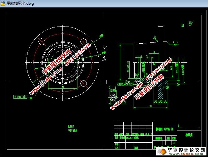
第六章 尾轮轴体的设计 15
6.1轴体的结构设计 15
6.2轴体的装配 15
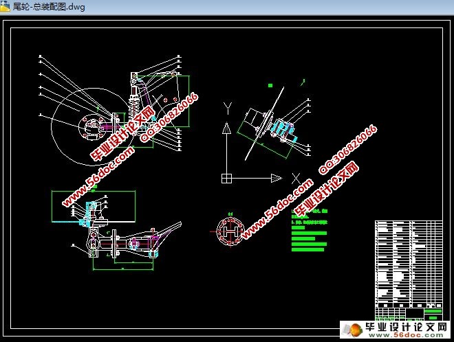
第七章 尾轮装置的总装配 17
7.1尾轮装置的零件 17
7.2尾轮装置的组装 17
结束语 18
参考文献 19
附录 20
致谢 22