接片倒装结构连续模的设计(含cad零件图和装配图)
无需注册登录,支付后按照提示操作即可获取该资料.
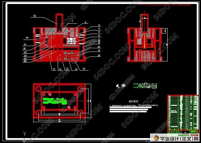
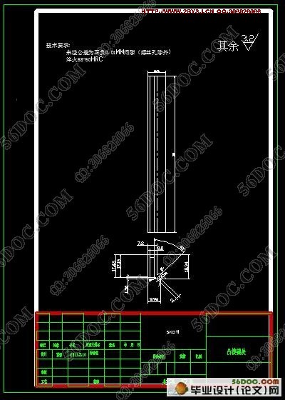
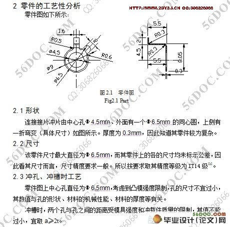
接片倒装结构连续模的设计(含cad零件图和装配图)(含选题审批表,任务书,开题报告,中期检查表,论文说明书11000字,CAD图纸22张)
摘 要:本次模具设计的零件为冲裁弯曲件。各工位有相互的尺寸关系,且尺寸的位置和精度要求较高,如果采用普通单工序模或复合模冲制生产的话,需要多副模具,多个操作人员才能完成而且产品质量和生产效率都低。采用多工位连续模可以提高材料利用率和模具的使用水平,节省设备,且保证了较高的产品质量和生产效率,以获得最佳的经济效益。本模具性能可靠,运行平稳,能够适应大批量生产要求,提高了生产质量和生产效率,降低了劳动强度和生产成本。
关键词:连续模;冲孔;落料;折弯;排样
Design of connection meet piece flip structure continuous mode
Abstract:This time the task of design is Punching Bending parts. There are mutual relationships between each part where higher accuracy of the size and location is required. If using the common single procedure or the composite modulus punch production, we need more moulds and operators. At the same time, the quality and the efficiency of our products are low. Selection of the Multi-Position Progressive Dies can improve the material utilization and the level of using molds. It also can save equipments and guarantee high quality and the efficiency of our products to get greatest economic benefits. This mould has reliable performance, and it can operate smoothly. In additon, it meets the requirements of mass production, which will improve the quality and the efficiency of our products, and also reduces labor intensity and production costs.
Key words: Progressive Dies; punch holes; fall the material curving; bcnding; arrangement
研究方案(研究目的、内容、方法、预期成果、条件保障等)
研究目的:通过对接片倒装结构的连续模的设计了解连续模多工位冲压原理
研究内容:1、连续模的工作原理与发展前景。
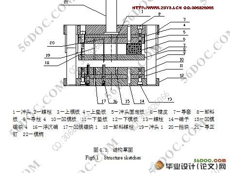
2、接片倒装结构连续模的总体设计(包括主要参数的确定,三视图的绘制,3D图的绘制和工作能力的确定等)
研究方法:结构分析法、文献资料法、经验法、计算法。
目 录
摘要 1
关键词 1
1 前言 2
2 零件的工艺性分析 2
2.1形状 2
2.2尺寸 3
2.3冲孔、冲槽时工艺 3
2.4表面质量 3
2.5材料性能 3
2.6制定冲压工艺方案 3
2.7条料宽度 4
3 材料利用率的计算 5
4 冲压力计算及设备选择 5
4.1冲裁力的计算 5
4.2卸料力的计算 6
4.3设备的选择 6
5 压力中心计算 7
6 模具结构草图 8
7 凹模的外形尺寸确定 9
8 冲裁间隙的确定 10
9 毛坯尺寸 10
9.1主要刃口尺寸计算 10
10 卸料装置的选用 11
11 模具零件设计 12
11.1工作凸、凹模设计 12
11.2导正孔凸模的设计及加工 12
11.3中心孔凸模设计 15
11.4冲槽凸模设计 17
11.5落料凸模设计 18
11.6其它零件设计 21
11.6.1 各用途的螺钉、销钉的选用 21
11.6.2模柄的选用 22
11.6.3模架的选用 22
11.6.4各模板的尺寸 22
11.6.5侧刃的设计 23
12 设备校核 23
12.1凸模抗压能力校核 23
12.2凸模纵向抗弯曲能力校核 24
12.3核对模具开模行程 24
13 结 论 25
参考文献 26
致 谢 27
