圆盘式剪板机的设计(含cad零件图和装配图)
无需注册登录,支付后按照提示操作即可获取该资料.
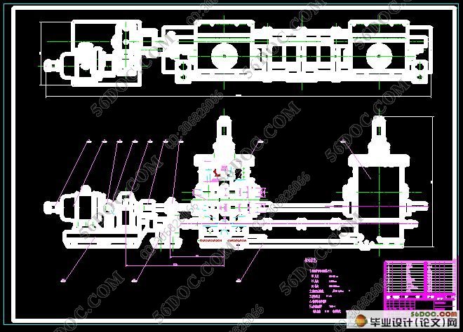
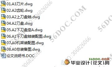
圆盘式剪板机的设计(含cad零件图和装配图)(论文说明书14000字,cad图纸8张)
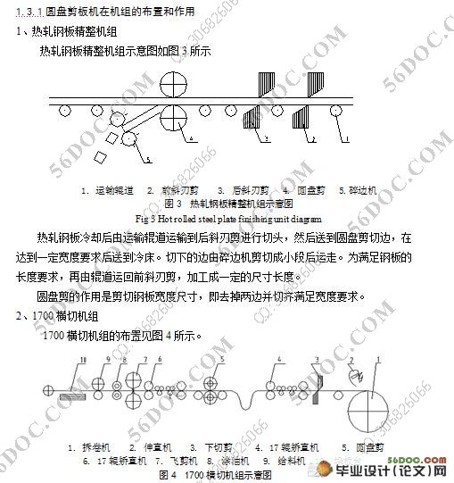
摘 要:圆盘剪板机通常设置在精整作业线上,用来将运动着的钢板的纵向边缘切齐或切成窄带钢。根据其用途可分为两种类型:剪切板边的圆盘剪和剪切带钢的圆盘剪。
本文中对圆盘剪板机的设计计算是从材料力学、动力学和经济学的角度出发,对圆盘剪板机的主传动系统,压下系统、侧间隙调整机构进行了设计。重点包括电动机的计算选取、轴和齿轮的设计,以及其他传动装置和执行机构的设计等,同时对部分主要零部件进行了强度校核。本次设计的改进点:首先,在径向间隙调整机构连杆机构,其二,侧向间隙调整增加自锁装置。其三,宽度调整采用行星齿轮减速机。最后增加了测速机构。本圆盘剪板机可普遍用于横切机组、酸洗机组等。
关键词:圆盘剪板机;带钢;压下装置;强度校核
The design of the disc alligrator shears
Abstract:Disc shear machine set up in finishing production line. It usually uses to cutting neat the movement steel plate longitudinal edge and cut the strip into narrow one. It can be divided into two kinds according to its use: disc shears of cut stencil plate’s side and disc shears of cut strip.
We have thorough understanding to the disc shears and the correlation equipment. We had very designed to the main transmission system, depress the system and gap adjustment organization, we are carry on these designs from the materials mechanics angle, dynamics and economic. The main content including electrical machinery selection, Axis and gear design, Implement agency design and so on, and the same time, we make the optimized improvement and the intensity examination to the major parts. The improvement spots in this design: First, in radial clearance adjusting mechanism link motion gear, second, backlash adjustment increase self-locking installment. Third, the width control uses the planet gear speed reducer. Finally increased has measured the fast organization. This disc shears may use in the transverse cutting unit, the acid pickling unit generally and so on.
Key words:Disc shear;Strip;Depress the system;The intensity examination


目 录
摘要…………………………………………………………………………………………1
关键词………………………………………………………………………………………1
1 前言 ……………………………………………………………………………………2
1.1 选题的背景和目的…………………………………………………………………2
1.2 圆盘式剪板机国内外的发展现状…………………………………………………2
1.3 圆盘剪板机研究的内容和方法……………………………………………………4
1.3.1 圆盘剪板机在机组的布置和作用……………………………………………4
1.3.2 圆盘剪板机的类型和特点……………………………………………………5
1.3.3 圆盘剪板机设计内容和方法…………………………………………………5
2 设计方案的选择和方案评述……………………………………………………………6
3 电机容量的计算…………………………………………………………………………7
3.1 定性选电机……………………………………………………………………………7
3.2 选择电动机的容量 …………………………………………………………………8
3.3 确定转速 ……………………………………………………………………………10
3.4 电动机的校核 ……………………………………………………………………11
4 主要零件强度计算校核…………………………………………………………………12
4.1 齿轮的计算与校核 …………………………………………………………………12
4.1.1齿轮的计算……………………………………………………………………12
4.1.2 按接触疲劳强度校核…………………………………………………………13
4.1.3 按弯曲疲劳强度校核…………………………………………………………16
4.2 传动轴的强度校核计算 ……………………………………………………………18
4.2.1轴的材料及其机械性能……………………………………………………… 18
4.2.2 轴的模型及传递功率的确定…………………………………………………18
4.2.3 按弯扭合成进行轴的强度校核………………………………………………19
4.2.4 按疲劳强度进行精确校核……………………………………………………21
4.3 轴承的选取及校核…………………………………………………………………24
4.3.1 根据工作条件选取轴承类型…………………………………………………24
4.3.2根据轴承结构确定轴承的型号………………………………………………25
4.3.3轴承的寿命校核………………………………………………………………25
4.3.4 验算轴承的极限转速…………………………………………………………27
4.4 键的选取及校核……………………………………………………………………27
4.4.1 键的尺寸的选择………………………………………………………………28
4.4.2 键的强度校核…………………………………………………………………28
5 联轴器的选择……………………………………………………………………………29
5.1联轴器的分类………………………………………………………………………29
5.2联轴器的选择 ………………………………………………………………………29
5.3联轴器的强度计算…………………………………………………………………29
6 系统的润滑………………………………………………………………………………30
6.1润滑剂的种类………………………………………………………………………30
6.2润滑方式的选择……………………………………………………………………30
6.3润滑方式的选择确定………………………………………………………………31
6.3.1 齿轮减速器的润滑方式………………………………………………………31
6.3.2 部分传动齿轮、轴承的润滑方式……………………………………………31
7 试车方法和对控制系统的要求…………………………………………………………31
7.1 试车要求 ……………………………………………………………………………31
7.2 对控制系统的要求 …………………………………………………………………31
8 设备可靠性与经济评价…………………………………………………………………32
8.1 机械设备的有效度…………………………………………………………………32
8.2 机械设备的投资回收期……………………………………………………………32
9 总结 ……………………………………………………………………………………33
参考文献……………………………………………………………………………………33
致谢…………………………………………………………………………………………34
