旋架式加速度过载模拟实验台结构设计(CAD,SolidWorks三维)☆
无需注册登录,支付后按照提示操作即可获取该资料.
旋架式加速度过载模拟实验台结构设计(CAD,SolidWorks三维)☆(含任务书,开题报告,外文翻译,论文说明书12000字,cad图纸,SolidWorks三维造型)
摘要:导弹等飞行器特别是对对空发射等高质量、高精度的武器,它们有很高的要求,要有很好的机动性能,导弹的机动性能越好,要求它的整体结构强度就越高,承受机动过载的能力越强,发动机的结构性能就要求越高,所以我们在生产使用前必须对一些参数进行实验性测试,这样才能保证它在高空过载情况下正常放心使用,并且保证其误差在允许范围内,因此,我们必须设计出相关仪器来测试出其参数, 因此,所以发动机过载模拟实验台产生了。
发动机过载模拟实验台是通过传动系统使固定在旋转架上的发动机转动而产生离心力,在过载情况下测试其某些性能参数的变化情况。通过离心机可以实现发动机内的弹道参数、离轴加速度、壳体应变以及温度等的测量.现主要工作就是系统的传动设计和测试件的夹紧。研究内容:了解该课题的特点以及发展状况.传动系统方案的设计、比较与确定.零件设计、选择、计算以及图纸的初步绘制,工件的夹紧方案的设计、比较与确定,生产部门讨论加工问题.
此次设计的实验台在不作点火的情况下,对可两个发动机进行测试,也可作单件测试。测试件一般在2m以内,重量不超过100㎏,具有结构简单、紧凑,工作可靠、维护方便等特点。实验台的设计目标是要满足地面普通热试车试验,在法向加速度作用下对飞行器进行性能检测,不至于导弹在机动飞行中失效。
关键字: 离心机、旋转台、发动机、过载、失效
Rack centrifugal acceleration to overload simulation design
Abstract: The aircraft such as missile is the high quality and precision weapon lauched by air to air .They have high requirement and have excellent maneuverability. The better maneuverability the missile have, the higher the intensity of holistic structure requires .The better it bear the mobile over loading,the higher the structure capability of engine requires.To ensure that the missile can run normally in the case of high-position and overloaded, and also make sure that error is under control. We must hold a experimental test to some parameter before it is made and used.Therefore, we must design relative apparatus to test parameter and the overload simulation laboratory bench of the engine has been designed..
The overload simulation laboratory bench of the engine is through the transmission system make the engine which install at the rotators shelf to rotate, that make the engine has the centrifugal force, tests its certain performance parameter change in the overload situation.pass left scheming can realize launch machine and leave the stalk acceleration, hull adapts to changes and the diagraph that temperature wait. Presently the main work is the system transmission design and measures the test sample clamping. The main study content include:learn the character of the task and the development trend,the design ,compare and confirmation of transmission system project, the design ,choice and calculate of part and the principium protract of blueprint. the design ,choice and calculate of the the project of clamp,the discussion of the problem of manufacture between production department.
This experiment pedestal of design under the condition of not make some fire, to can two launch the machine to carry on the test, also can make a test.Test the piece generally at 2 m in, weight not over 100 Kg, have the structure simple, tightly packed, work dependable, support the convenience etc. characteristics. The aim of the design of this laboratory bench is to satisfy the common hot test-drive on the ground and to test the capability of the aircraft with the function of the vertical acceleration. The missile will not invalidation under this condition
Keywords:Leave the scheming revolve the set deliver the motive over loading invalidation
毕 业设计(论文)使用的原始资料(数据)及设计技术要求:
设计一个测试导弹空中飞行过程中离心加速度的加速度过载模拟实验台,主要
技术条件:待测件重量35kg,直径120-150mm,长度1000-2000mm,最大离心加速度
70g。要求进行转台的结构设计,并进行相应的强度计算。
2 实验台的总体方案设计
2.1技术参数设计
2.1.1 待测件结构尺寸设计
本试验台应该适应以下发动机试验要求:
1)过载模拟(单台或双台发动机)
2)发动机不点火试验
3)待测件长度:1000 ~2000mm
4)待测件直径:120 ~150mm
5)待测件重量: 35Kg
2.1.2 待测件载荷设计
最大离心加速度:70g
旋转架承载能力:不低于15000N
2.1.3 转台运动参数设计
转台采用变频调速方式,技术指标:
旋转架转速:小于300r/min
旋转架启动平稳时间:180S
电机额定功率:5.5KW
上面装有压力应变片,并且配有控制箱,具有安全措施保障人员安全
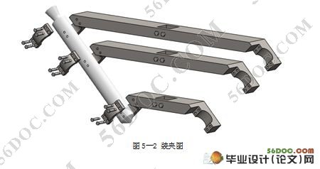
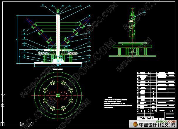
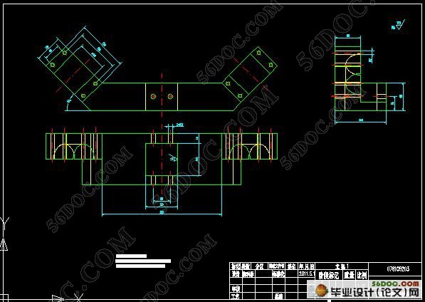
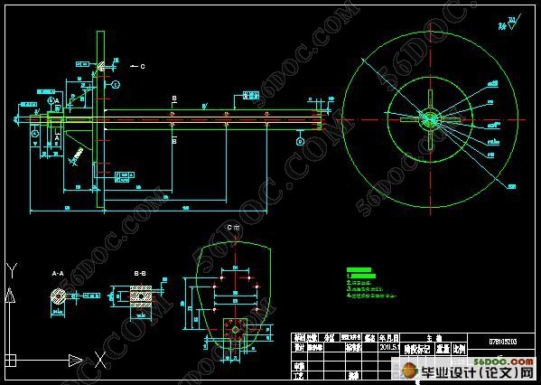
#p#副标题#e#
目 录
1 前言
1.1 选题的意义………………………………………………………………………(1)
1.2 国内外发展状况…………………………………………………………………(4)
1.3 论文的主要内容 ………………………………………………………………(5)
2 实验台的总体方案设计
2.1 技术参数设计 …………………………………………………………………(5)
2.2 总体方案的提出以及特点 ……………………………………………………(6)
3 实验台结构设计
3.1 电动机的选择 …………………………………………………………………(8)
3.2 装配图的设计 ………………………………………………………………(10)
3.3 带传动的选择与计算 ………………………………………………………(11)
3.4 轴的设计 ……………………………………………………………………(12)
3.5 底座的设计 …………………………………………………………………(16)
3.6 立柱的设计 …………………………………………………………………(17)
4 主要零件的设计验算
4.1 轴的校核 ……………………………………………………………………(18)
4.2 轴承的选择与校核 …………………………………………………………(25)
4.3 螺栓与螺钉的选择与校核 …………………………………………………(27)
4.4 键的选择与校核 ……………………………………………………………(28)
5 工件的夹紧
5.1工件的夹紧的要求 …………………………………………………………(29)
5.2方案 ……………………………………………………………………………(29)
参考文献……………………………………………………………………………(31)
小 结 ………………………………………………………………………………(32)
致 谢 ………………………………………………………………………………(32)
