简易吊车的设计(附cad零件图和装配图)
无需注册登录,支付后按照提示操作即可获取该资料.
简易吊车的设计(附cad零件图和装配图)(含开题报告,论文说明书13000字,10张cad图纸)
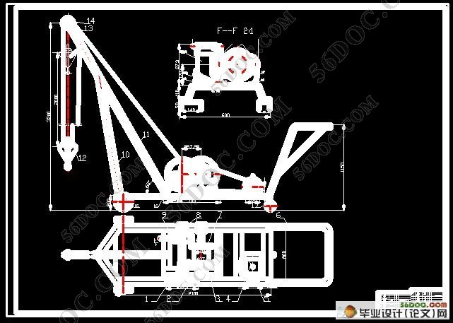
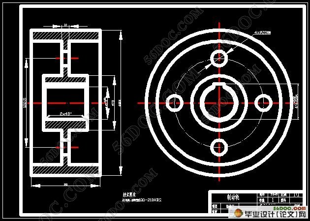
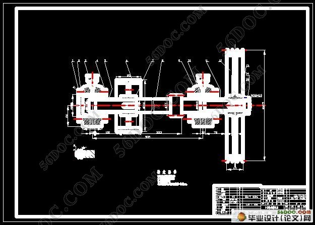
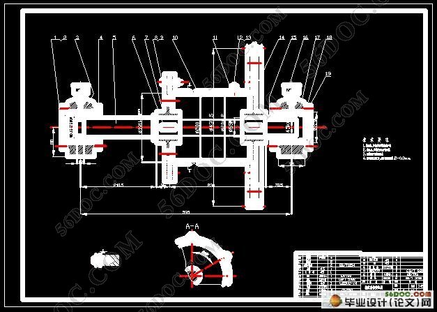
摘 要:本课题的目的就是设计一简易吊车来代替人力实现重物的搬运。该吊车的工作原理是:由电动机经带轮传动和一对开式齿轮传动,将运动和动力传给卷筒,再通过钢丝绳和滑轮组来提升重物。通过任务书中的条件参数,设计计算相关的数据,选择钢丝绳的种类和型号,进而计算出卷筒和滑轮的直径,确定一些其它的标准零部件。在此基础上进行传动装置的设计和计算,完成其进行结构设计,工作主要包括完成了轴的设计、确定了带轮的结构、齿轮的结构、卷筒的结构、滑轮的结构 、伸臂杆和支撑杆的结构,绘制了绘制了吊车的总装配图、制动轮装置和卷筒装置的结构图,完成部分零件工作图的设计。
关键词:简易吊车;设计计算;结构设计
Design of The Simple Cable Car
Abstract: The purpose of this project is to design a simple realization of the cable car to replace the human handling of heavy weights. The working principle of the cable car is: by the motor via a pulley drive and gear drive off, the movement and momentum to the drum, and then through the rope and pulleys to raise heavy objects group. Conditions through the parameters of the task book, design and calculation of relevant data, select the type and model of wire rope, and then calculated the diameter of the drum and pulley, to identify a number of other parts of the standards. Carried out on the basis of gear design and calculation, to complete its structural design, primarily include the completion of the design of the shaft to determine the structure of the pulley, the gear structure of the drum structure, block structure, under and the supporting bar of the structure, rendering a total mapping of the crane assembly, brake drum round of devices and device structure, the completion of the work of some parts of the design plans.
Keyword: Simple cable car; Calculation; Structural Design

#p#副标题#e#
目 录
摘要 ……………………………………………………………………………1
关键词 …………………………………………………………………………1
1前言 …………………………………………………………………………2
1.1 吊车的历史………………………………………………………………3
1.2 吊车国内外的研究现状…………………………………………………3
1.3 吊车的发展趋势 ………………………………………………………3
2工作机构的设计 ……………………………………………………………5
2.1 钢丝绳的选择……………………………………………………………5
2.1.1 钢丝绳的种类……………………………………………………5
2.1.2 钢丝绳的型号 …………………………………………………6
2.1.3 钢丝绳直径的选择 ……………………………………………7
2.2 卷筒和滑轮直径的选择…………………………………………………7
3传动装置的设计和计算 ……………………………………………………8
3.1 计算卷筒的功率 ……………………………………………………… 8
3.2 计算卷筒的转速 ……………………………………………………… 9
3.3 电动机的选择 ………………………………………………………… 9
3.3.1 电动机类型的选择 …………………………………………… 9
3.3.2 电动机转速的选择 …………………………………………… 9
3.3.3 电动机功率的选择…………………………………………… 10
3.4 计算总传动比 ……………………………………………………… 10
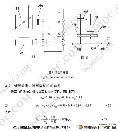
3.5 确定传动方案,画出传动示意图 ………………………………… 11
3.6 分配传动比 ………………………………………………………… 11
3.7 计算效率,验算电动机的功率 ………………………………………12
3.8 计算各轴的转速、功率和转矩 ………………………………………12
3.9 制动器的选择 …………………………………………………………14
3.10 传动机构的设计和计算 …………………………………………… 15
3.10.1 带传动 ……………………………………………………… 15
3.10.2 齿轮传动 …………………………………………………… 17
3.11 画出总体结构方案图 ………………………………………… 18
4结构设计 ………………………………………………………………… 20
4.1 初算各轴的最小直径 …………………………………………………20
4.2 带轮的结构 ……………………………………………………………20
4.3 齿轮的结构 ……………………………………………………………21
4.4 卷筒的结构 ……………………………………………………………22
4.5 滑轮的结构 ……………………………………………………………23
4.6 升臂杆和支撑杆的结构 ………………………………………………23
4.6.1 升臂杆和支撑杆的尺寸 ……………………………………23
4.6.2 根据强度条件、决定升臂杆的材料和断面尺寸………………24
4.6.3 根据强度条件,决定支撑杆的材料和断面尺寸 ……………26
4.7 画制动轮装置和卷同装置的结构图 …………………………………26
4.8 绘制吊车的总装配图 …………………………………………………27
4.9 拆画重要零件图 ………………………………………………………27
5设计小结 …………………………………………………………………27
5.1 小结 ……………………………………………………………………27
5.2 设计心得 ………………………………………………………………27
参考文献 ………………………………………………………………………29
致 谢……………………………………………………………………………30
