
��ˮ��Ͳ��Ⱥ�ӹ���ϻ������
����ע���¼,֧��������ʾ�������ɻ�ȡ������.
��ˮ��Ͳ��Ⱥ�ӹ���ϻ������(cadͼֽ������˵����17000��)
ժ Ҫ
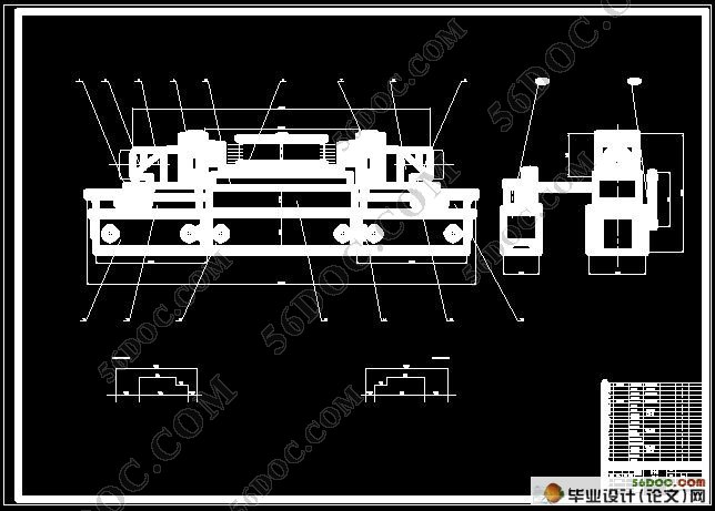
��������ϸ��������ϻ�������Ʋ��裬��ϻ�����һ�ָ�Ч�ʵ�ר�û��������㷺Ӧ���ڻ�е������ҵ�������������Ҫ�����DZ�����Ƶ���Ŀ�ǣ���ˮ��Ͳ��Ⱥ�ӹ�����ϻ�����ƣ�����12-Ø5�ף��ܹ�432����ʵ��˫��λ�ӹ���
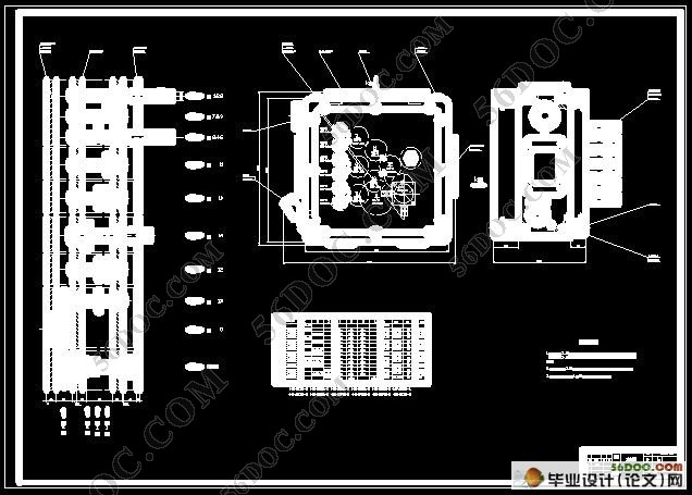
������ҵ���������������֣�ȷ���ӹ�ʱ������������������ع�ʽ�������������ѡ����Ӧ��Һѹ��̨��������������ʣ�ѡ������͵綯�������������ת�أ�ѡ����ʵ�����ֱ���͵��ߡ����ݼӹ����Ҫ���Ƴ���ϻ����ġ���ͼһ�����������ӹ�����ļӹ�����ͼ���ӹ�ʾ��ͼ����ϻ����ߴ���ϵͼ�Լ������ʼ��㿨�����ݹ����Ͽķֲ�����Ƴ�����ϵͳͼ��Ϊ������������Ƿ����˸��棬����������ͼ�������ƶ�������ͼ��Ϊ�� ��֤����ڼӹ�������ȷ��λ��Ӧ���һ�оߡ�
Һѹ����ϵͳ������������ҪΪ��ȷ���Ҫ���ƶ���������������Һѹϵͳͼ������ȷ��Һѹϵͳ����Ҫ������Һѹϵͳ����Ҫ���������غɵ���ɺͼ��㣬����Һѹ����Ҫ�ṹ�ߴ磬������ҺѹԪ����ѡ������Լ�ר�ü�Ҳ�������ؿ��ǡ�
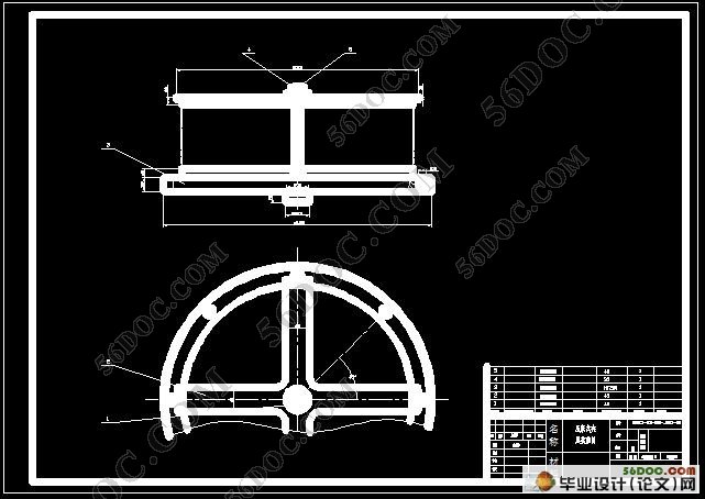
������ˮ��Ͳ��Ⱥ�ӹ��Ĺ��������Ҫ���������������ԣ�������моߵ���ƣ����ڹ������н��Ϸ��㣬�ʲ����ֶ�װ�ã����øǰ�����ѹ�ļн���ʽ�����������ƽ��мн����ɿ����Ա��������Ч�ʡ�
����ϵͳ����ƾ������û��紫����֪ʶ����PLCϵͳ���п��ƣ�PLC����ϵͳ�����⣬ŷķ��ϵͳ�ȡ�
�ؼ��ʣ���ϻ��� ��ͼһ�� ������ ����ѹ���о� PLC CAD
Abstract
This article detailed introduction makes up the design measure of the lathe .It is a kind of high �Cefficient special purpose lathe to make up the lathe ,is widely used in the mechanical manufacturing industry . According to the request of task book,to process a serious of holes , which is the tube of machine of dehydration and the diameter is 5. Originally design and stsrt with analysing the processing technology of the part ,determine the cutting quantity while processing ,calculate out the strength of cutting according to relevant formulace , calculate out the power of cutting as choosing the motive force case ,the basis of the electrical machinery ;calculate out and cut the torque,is elected the suitable diameter and cutter of main staft . Require according to processing of part , draw out and make up three pictures first calorie of lathe , Namely process into part process picture , processing sketch map ,lathe get in touch with size picture .and productivity calculate the card .According to the distribution of the hole on the work piece ,design the transmission picture .In order to interfere each other while checking every part ,express the outlines of various kinds of parts with different linear and colours .Draw out many axle case general drawing finally .For guarantee part accurate to confirm location clamp ,should design one retinue jig in processing .According to the actual conditions ,we design the spiral push mechanism of a set of drill .Draws the lathe and gets in touch with the size picture with finally .
According to dehydrates the cylinder wall group hole processing working procedure production request, the batch, the craft characteristic, but also must carry on the jig the design, because the work piece is simple, clamps conveniently, therefore uses the hand gear, uses the lap spiral spinning to clamp the way, about turns on lathe the thread to carry on clamps with the pine opens, in order to enhancement production efficiency.
The electrical system design is the utilization mechanical and electrical transmission knowledge, namely the PLC system carries on the control, the PLC control system has Mitsubishi, the ohm dragon system and so on.
Keywords Combinated-lathe Three picture and one card Many axle cases The spiral push mechanism PLC CAD
1 ��Ʒ����
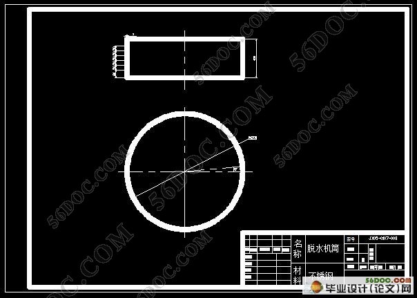
��ˮ��Ͳ�ǹ�ҵ����ˮ���Ĺؼ���ɲ��֣���ˮ��Ͳ���������ӣ�ֱ�ӹ�ϵ����ˮ�����������ӣ���ˣ����������ǰ�ص��߷��������ʹ�����һ�ҹ�ҵ��ˮ���������̣���������ȡ�˽��ܡ�����Ʒ���ò�����ƣ����Ϊb=5����H=400����Բֱ��ΪØ 1200.
2����Ĺ����Լ�����Ҫ��
���������Ҫ�Ǽӹ���ˮ��Ͳ�ڵ�432- Ø5�ף���ϻ���˫������ӹ���ÿ������12- Ø5�ף�����̨��תתλ�ֶȣ�ÿ��5�㣬�ֲڶȱ�֤6.3������̨��ת��������0.5�㣬������λ��ȡһ��Ͷ�����λ������5�����ɶȡ�
3ë�����������췽����ѡ��
����ʵ�����������ʵ����Ҫ�����������ˮ��Ͳ�ڵ�ë������ѡ��Ϊ����֣���ȡģ�ͳ��ͣ����˻�����
����������ˮ��Ͳ��Ⱥ�ӹ�������ϻ���˫��λ�ӹ���������������ʡ�

Ŀ¼�뿴��һҳ
#p#������#e#
Ŀ ¼
ժҪ����������������������������������������������������.��������1
Abstract����������������������������������������������������..����..2
ǰ�ԡ���������������������������������������������������..����...3
��һ �� ��ϻ������� ����������...������������������������������.��7
�ڶ��� ��ϻ���������ơ�����������������������������������..��.....8
2.1���շ������ⶩ������������������������������������������.��.��..8
2.1.1��Ʒ���ܡ�����������������������������������������������.��....8
2.1.2����Ĺ����Լ�����Ҫ����������������������������������.��8
2.1.3 ë�����������췽����ѡ��. ������������������������...������.��...8
2.1.4 �ⶩ���տ�Ƭ������������������������������������������..��.8
2.2 �����о���ơ�������������������������������������������..��9
2.2.1 �����о���Ƹ�������������������������������������������...9
2.2.2 �о���ƻ���Ҫ��������������������������������������...9
2.2.3�о���Ƶķ����Ͳ��衭������������������������������������9
2.3 ����������ȷ����������������������������������������������12
2.3.1 ��ϻ���ȴ��������ȷ����������������������������������.....12
2.3.2 ȷ��������������ת��.���������Լ��������ö� ����������..��13
2.4 ��ϻ�������ͼһ������������������������������������������13
2.4.1���ӹ��������ͼ��������������������������������������..����..13
2.4.2 ���ӹ�����ӹ�ʾ��ͼ����������������������������������������14
2.4.3 �����ߴ���ϵͼ ��������������������������������������.��..��...15
2.4.4 �����ʼ��㿨����������������������������������������.����17
���� �¡���ϻ�����������ơ�������������������������������.��18
3.1.������ͨ�ö��������ɼ�����﷽������������������������.��18
3.2 ������ͨ�������������������������������������������������18
3.2.1 ͨ�������������������������������������������������.����18
3.2.2 ͨ�����ᡭ������������������������������������������������86
3.2.3 �������ѡ��������������������������������������������18
3.3 ͨ�ö�������ơ�������������������������������������������........18
3.3.1 ���ƶ��������ͼ�Լ�ԭʼ����ͼ����������������������������.��18
3.3.2 ������ֵ�ȷ���Լ��������㡭��������������������������.��.��.. 19
3.3.3 �����䴫��ϵͳ����������������������.����������������������.. 19
3.3.4 ������������㣬����������ͼ������������������������.���� ��20
������ Һѹϵͳ����Ƽ��㡭������������������������������������23
4.1.��Һѹ����Ƽ��㲽�衭������������������������������.������.....23
4.2 Һѹ�����ܲ������㡭������������������������������.����..........23
4.2.1 Һѹ���������������������������������������������������..23
4.2.2Һѹ������ٶȼ��㡭��������������������������������������...23
4.2.3 Һѹ������ʱ�䡭����������������������������.����������.....24
4.3 Һѹ����Ҫ����ߴ硭��������������������������������������.....25
4.3.1 Һѹ���ھ����㡭������������������������������������.���� ��25
4.3.2 Һѹ��ֱ���ļ��㡭������������������������������������.����.. ..25
4.3.3 Һѹ���г̵�ȷ����������������������.������������������. ����..25
4.4 �ṹǿ�ȼ����Լ��ȶ���У�ˡ���������������������������������26
4.4.1.����Ͳ�⾶��ȷ��������������������������������������������..26
4.4.2 Һѹ���ȶ����Լ������˵�ǿ�ȼ��㡭��������������������....26
4.4.3 Һѹ�Ľṹ��ơ�������������������������������������..����27
4.4.4 Һѹ����ϵͳ��ơ���������������������������������������.��28
4.4.5 ��ȷ���Ҫ��������������������������������������������28
4.4.6 �ƶ�Һѹϵͳ����������������������������������������������....29
4.6 ����װ�õ�ѡ���������������������� ������������������.��.��30
4.7 ����Һѹϵͳͼ������������������������ ��������������������..��30
������ ����ϵͳϵͳ��ơ���������������������������������..��...31
5.1 �����豸����������������������������������������������.��.....31
5.1.1 PLC�Ļ�����ϡ�����������������������������������...������..31
5.1.2 �������Ʊ�ѹϵͳ������ơ���������������������������.��..��....31
5.1.3�������ƵIJ�����ơ��������������������������� ������...����....31
5.2OMRON,CPM2Aϵ��PLC���ܽ��ܡ�����������������������........33
5.3 �����豸�ĸ�����������������������������������������.������...34
5.3.1 ѡ�ú�ȷ��I/O�豸����������������������������������.��...��...34
5.3.2ѡ��PLC���ͺ��Լ�����������������������������������..��....34
5.4 ���Ƴ�����ơ�������������������������������������������....35
���ۡ���������������������������������������������������...������..37
л�ǡ�����������������������������������������������������.��.��..38
�ο������븽¼����������������������������.��������..��....��������...39